How to Use Prototype Board (BACK): Examples, Pinouts, and Specs
Introduction
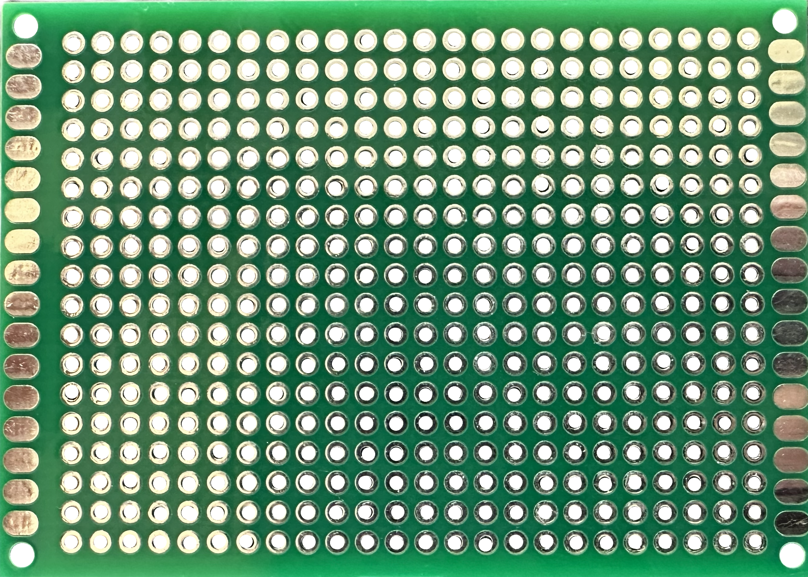
A prototype board, commonly referred to as a breadboard, is a reusable platform designed for building and testing electronic circuits without the need for soldering. The back side of a prototype board often includes additional features such as power rails, mounting holes, or adhesive backing, which enhance its usability in various applications. These boards are widely used in prototyping, educational projects, and temporary circuit setups.
Explore Projects Built with Prototype Board (BACK)

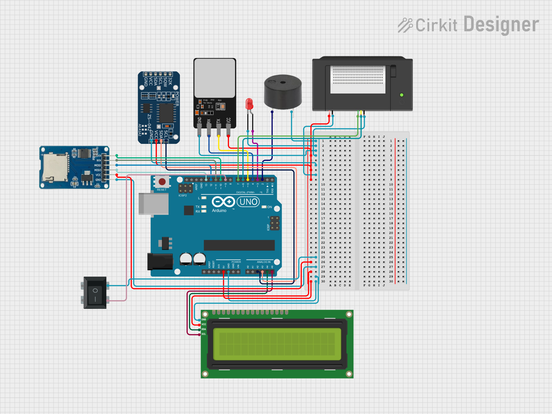
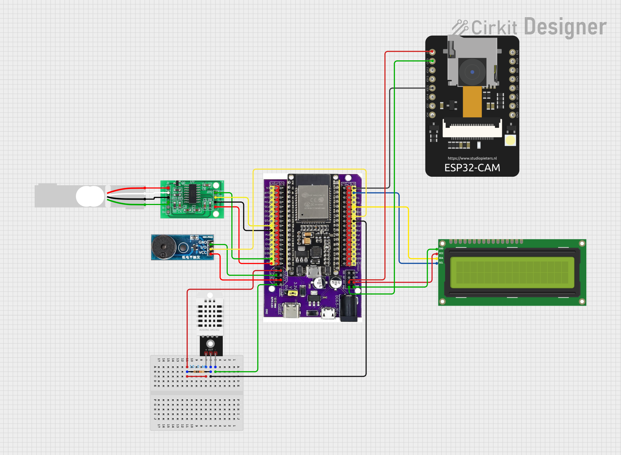
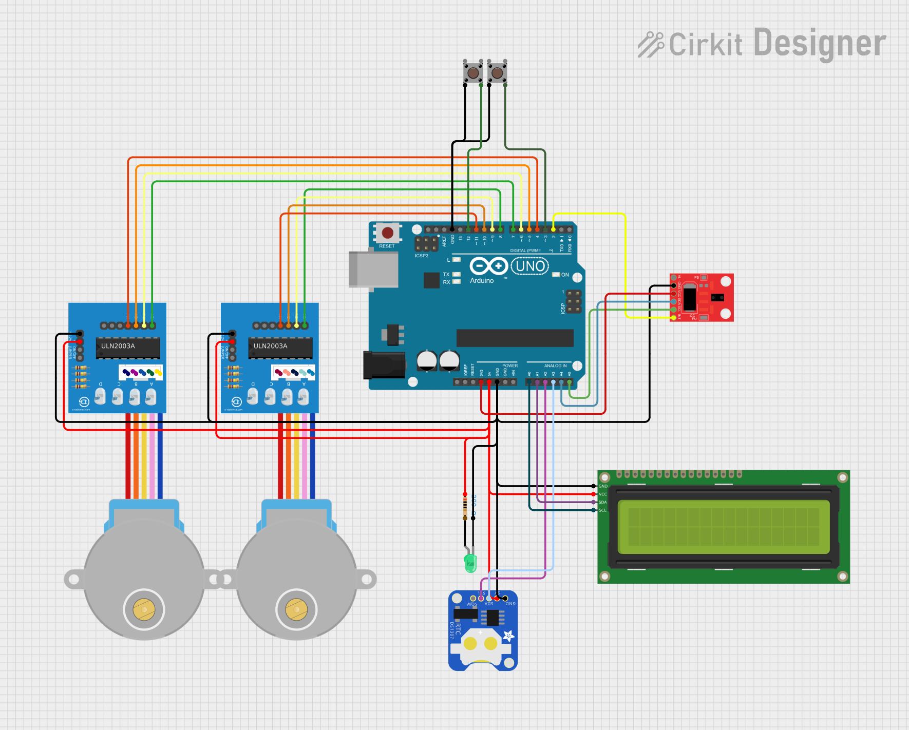
Explore Projects Built with Prototype Board (BACK)
Common Applications and Use Cases
- Rapid prototyping of electronic circuits
- Educational purposes for learning circuit design
- Temporary circuit assembly for testing and debugging
- Integration with microcontrollers like Arduino or Raspberry Pi
- Experimentation with sensors, LEDs, and other components
Technical Specifications
The back side of a prototype board may vary depending on the model, but it typically includes features that support the front-side connections. Below are the general specifications:
Key Technical Details
| Feature | Description |
|---|---|
| Material | ABS plastic with metal contact strips |
| Dimensions | Common sizes include 170x55mm, 830x60mm, or larger |
| Adhesive Backing | Some models include a peel-and-stick adhesive layer for mounting |
| Mounting Holes | Pre-drilled holes for securing the board to a surface |
| Power Rails | Extended connections for distributing power across the board |
| Operating Temperature | -40°C to 85°C |
| Reusability | Designed for repeated use without degradation |
Pin Configuration and Descriptions
While the back side of a prototype board does not have traditional pins, it supports the following features:
| Section | Description |
|---|---|
| Power Rails | Metal strips running along the edges for connecting power and ground |
| Terminal Strips | Metal strips underneath the board for connecting components in rows |
| Adhesive Layer | Optional sticky backing for mounting the board on a flat surface |
| Mounting Holes | Holes for screws or bolts to secure the board |
Usage Instructions
How to Use the Prototype Board (Back)
- Inspect the Back Side: Check for adhesive backing or mounting holes. If adhesive is present, peel off the protective layer and stick the board to a flat surface. If mounting holes are available, use screws or bolts to secure the board.
- Connect Power Rails: Use the power rails on the back side to distribute power and ground connections across the board.
- Insert Components: Place components such as resistors, capacitors, or ICs into the front-side holes. The back-side metal strips will establish electrical connections.
- Integrate with Microcontrollers: Connect the prototype board to a microcontroller like an Arduino UNO using jumper wires.
Important Considerations and Best Practices
- Avoid Overloading: Do not exceed the current or voltage ratings of the metal strips to prevent overheating.
- Check Connections: Ensure that components are securely inserted into the holes to maintain reliable connections.
- Use Proper Mounting: If using the adhesive backing, ensure the surface is clean and dry for a strong bond.
- Label Connections: For complex circuits, label the power rails and component connections to avoid confusion.
Example: Connecting to an Arduino UNO
Below is an example of how to use a prototype board with an Arduino UNO to light up an LED:
// Example: Blink an LED using Arduino and a prototype board

// Define the pin connected to the LED
const int ledPin = 13;

void setup() {
  pinMode(ledPin, OUTPUT); // Set the LED pin as an output
}

void loop() {
  digitalWrite(ledPin, HIGH); // Turn the LED on
  delay(1000);                // Wait for 1 second
  digitalWrite(ledPin, LOW);  // Turn the LED off
  delay(1000);                // Wait for 1 second
}
Circuit Setup:
- Connect the Arduino's GND pin to the prototype board's ground rail.
- Connect the Arduino's pin 13 to one leg of the LED (via a 220-ohm resistor).
- Connect the other leg of the LED to the ground rail.
Troubleshooting and FAQs
Common Issues
- Loose Connections: Components may not make proper contact with the metal strips.
- Solution: Ensure components are fully inserted into the holes and check for bent leads.
- Short Circuits: Adjacent rows may accidentally connect, causing a short circuit.
- Solution: Double-check the placement of components and wires to avoid unintended connections.
- Adhesive Failure: The adhesive backing may lose its stickiness over time.
- Solution: Use double-sided tape or screws through the mounting holes to secure the board.
FAQs
Q: Can I solder components to a prototype board?
A: No, prototype boards are designed for temporary, solder-free connections. For permanent circuits, use a solderable perfboard.
Q: How do I clean the back side of the board?
A: Use a soft, dry cloth to remove dust. Avoid using liquids, as they may damage the adhesive or metal strips.
Q: Can I cut the board to a smaller size?
A: Yes, some prototype boards can be cut, but this may damage the internal connections. Use caution and ensure the cut section still functions as intended.
By following this documentation, you can effectively use the back side of a prototype board to enhance your circuit-building experience.