Cirkit Designer Logo
Cirkit Designer
Your all-in-one circuit design IDE
Home / 
Component Documentation

How to Use PS2 Connector: Examples, Pinouts, and Specs

Image of PS2 Connector
Cirkit Designer LogoDesign with PS2 Connector in Cirkit Designer

Introduction

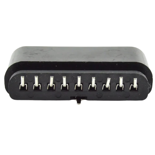
The PS2 connector, manufactured by Arduino with part ID PS2, is a 6-pin mini-DIN connector used primarily for connecting keyboards and mice to computers. Although it has largely been replaced by USB in modern systems, the PS2 connector remains relevant in various legacy systems and specific applications where low-latency input is crucial.

Explore Projects Built with PS2 Connector

Use Cirkit Designer to design, explore, and prototype these projects online. Some projects support real-time simulation. Click "Open Project" to start designing instantly!
Raspberry Pi Pico-based PS2 Controller Emulator with ADS1115 Analog Input
Image of PS2Pico: A project utilizing PS2 Connector in a practical application
This circuit appears to be a game controller interface that uses a Raspberry Pi Pico microcontroller to emulate a PS2 controller, interfacing with a PS2 joystick and a PS2 console cable. The ADS1115 analog-to-digital converter is used to read the joystick's analog signals, and the microcontroller's SPI and I2C interfaces are utilized for communication with the PS2 console and the ADS1115, respectively. Additionally, an NPN transistor and a resistor are configured to handle the PS2 controller's acknowledge signal.
Cirkit Designer LogoOpen Project in Cirkit Designer
Pushbutton-Controlled Interface with 40-Pin Connector and UBS Power Supply
Image of connect 4: A project utilizing PS2 Connector in a practical application
This circuit consists of a 40-pin connector interfacing with four pushbuttons and a UBS power supply. The pushbuttons are used as inputs to the connector, which then relays the signals to other components or systems. The UBS power supply provides the necessary 24V power to the pushbuttons and the common ground for the circuit.
Cirkit Designer LogoOpen Project in Cirkit Designer
24V Pushbutton Control Interface with 40-Pin Connector
Image of 4 på rad: A project utilizing PS2 Connector in a practical application
This circuit consists of a 24V power supply unit (PSU) connected to four pushbuttons. Each pushbutton is wired such that pressing it will send a 24V signal to a corresponding general-purpose input (GP In) on a 40-pin connector. The common return path for the pushbuttons is connected to the 0V of the PSU, which is also connected to the common (Com) for input pins on the 40-pin connector, completing the circuit for each button press.
Cirkit Designer LogoOpen Project in Cirkit Designer
5-Pin Connector Synchronization Circuit
Image of UMB_Cable: A project utilizing PS2 Connector in a practical application
This circuit consists of four 5-pin connectors, where two of the connectors are fully interconnected pin-to-pin. The purpose of this setup could be to create a parallel connection between the two 5-pin connectors, possibly for signal distribution or redundancy.
Cirkit Designer LogoOpen Project in Cirkit Designer

Explore Projects Built with PS2 Connector

Use Cirkit Designer to design, explore, and prototype these projects online. Some projects support real-time simulation. Click "Open Project" to start designing instantly!
Image of PS2Pico: A project utilizing PS2 Connector in a practical application
Raspberry Pi Pico-based PS2 Controller Emulator with ADS1115 Analog Input
This circuit appears to be a game controller interface that uses a Raspberry Pi Pico microcontroller to emulate a PS2 controller, interfacing with a PS2 joystick and a PS2 console cable. The ADS1115 analog-to-digital converter is used to read the joystick's analog signals, and the microcontroller's SPI and I2C interfaces are utilized for communication with the PS2 console and the ADS1115, respectively. Additionally, an NPN transistor and a resistor are configured to handle the PS2 controller's acknowledge signal.
Cirkit Designer LogoOpen Project in Cirkit Designer
Image of connect 4: A project utilizing PS2 Connector in a practical application
Pushbutton-Controlled Interface with 40-Pin Connector and UBS Power Supply
This circuit consists of a 40-pin connector interfacing with four pushbuttons and a UBS power supply. The pushbuttons are used as inputs to the connector, which then relays the signals to other components or systems. The UBS power supply provides the necessary 24V power to the pushbuttons and the common ground for the circuit.
Cirkit Designer LogoOpen Project in Cirkit Designer
Image of 4 på rad: A project utilizing PS2 Connector in a practical application
24V Pushbutton Control Interface with 40-Pin Connector
This circuit consists of a 24V power supply unit (PSU) connected to four pushbuttons. Each pushbutton is wired such that pressing it will send a 24V signal to a corresponding general-purpose input (GP In) on a 40-pin connector. The common return path for the pushbuttons is connected to the 0V of the PSU, which is also connected to the common (Com) for input pins on the 40-pin connector, completing the circuit for each button press.
Cirkit Designer LogoOpen Project in Cirkit Designer
Image of UMB_Cable: A project utilizing PS2 Connector in a practical application
5-Pin Connector Synchronization Circuit
This circuit consists of four 5-pin connectors, where two of the connectors are fully interconnected pin-to-pin. The purpose of this setup could be to create a parallel connection between the two 5-pin connectors, possibly for signal distribution or redundancy.
Cirkit Designer LogoOpen Project in Cirkit Designer

Common Applications and Use Cases

  • Legacy Computer Systems: Connecting keyboards and mice to older computers.
  • Embedded Systems: Low-latency input for specialized applications.
  • DIY Electronics Projects: Interfacing with older peripherals.
  • Industrial Control Systems: Reliable and robust input connections.

Technical Specifications

Key Technical Details

Parameter Value
Voltage 5V DC
Current 10-20 mA
Power Rating 0.1W
Connector Type 6-pin mini-DIN
Manufacturer Arduino
Part ID PS2

Pin Configuration and Descriptions

Pin Number Name Description
1 Data Serial data line
2 Not Used Not connected
3 GND Ground
4 VCC +5V power supply
5 Clock Clock signal for data synchronization
6 Not Used Not connected

Usage Instructions

How to Use the Component in a Circuit

  1. Power Supply: Connect the VCC pin (Pin 4) to a 5V power supply and the GND pin (Pin 3) to the ground.
  2. Data Lines: Connect the Data pin (Pin 1) and Clock pin (Pin 5) to the corresponding data and clock lines of your microcontroller or computer.
  3. Unused Pins: Ensure that the unused pins (Pin 2 and Pin 6) are not connected to avoid any interference.

Important Considerations and Best Practices

  • Signal Integrity: Use short and shielded cables to minimize noise and signal degradation.
  • Power Supply: Ensure a stable 5V power supply to avoid erratic behavior.
  • Pull-up Resistors: Use appropriate pull-up resistors on the Data and Clock lines if required by your microcontroller.

Example: Connecting to an Arduino UNO

To connect a PS2 keyboard to an Arduino UNO, you can use the following example code:

#include <PS2Keyboard.h>

// Define the pins for the PS2 Data and Clock lines
const int DataPin = 8;
const int ClockPin = 9;

PS2Keyboard keyboard;

void setup() {
  Serial.begin(9600);
  keyboard.begin(DataPin, ClockPin);
  Serial.println("PS2 Keyboard Test:");
}

void loop() {
  if (keyboard.available()) {
    char c = keyboard.read();
    Serial.print(c);
  }
}

Troubleshooting and FAQs

Common Issues Users Might Face

  1. No Response from Keyboard/Mouse:

    • Solution: Check the power supply connections and ensure that the VCC and GND pins are correctly connected.
    • Tip: Verify that the Data and Clock lines are connected to the correct pins on the microcontroller.
  2. Erratic Behavior:

    • Solution: Ensure that the power supply is stable and free from noise.
    • Tip: Use short, shielded cables to minimize interference.
  3. Data Corruption:

    • Solution: Check for proper grounding and signal integrity.
    • Tip: Use pull-up resistors on the Data and Clock lines if necessary.

FAQs

Q: Can I use the PS2 connector with modern computers? A: While modern computers primarily use USB, you can use a PS2-to-USB adapter to connect PS2 peripherals to USB ports.

Q: What is the maximum cable length for a PS2 connection? A: The maximum recommended cable length is around 6 feet (1.8 meters) to ensure signal integrity.

Q: Do I need any special libraries to use the PS2 connector with Arduino? A: Yes, you can use the PS2Keyboard library for interfacing with PS2 keyboards.


This documentation provides a comprehensive overview of the PS2 connector, including its technical specifications, usage instructions, and troubleshooting tips. Whether you are a beginner or an experienced user, this guide will help you effectively utilize the PS2 connector in your projects.