Cirkit Designer Logo
Cirkit Designer
Your all-in-one circuit design IDE
Home / 
Component Documentation

How to Use Qwiic Cable - Breadboard Jumper (4-pin): Examples, Pinouts, and Specs

Image of Qwiic Cable - Breadboard Jumper (4-pin)
Cirkit Designer LogoDesign with Qwiic Cable - Breadboard Jumper (4-pin) in Cirkit Designer

Introduction

The Qwiic Cable - Breadboard Jumper (4-pin) is an essential component designed to facilitate seamless and solderless connections between Qwiic-enabled devices and a standard breadboard. This cable is particularly useful for rapid prototyping, educational purposes, and hobbyist projects where ease of use and flexibility are paramount. Common applications include interfacing sensors, actuators, and modules with microcontrollers such as the Arduino UNO in a plug-and-play fashion.

Explore Projects Built with Qwiic Cable - Breadboard Jumper (4-pin)

Use Cirkit Designer to design, explore, and prototype these projects online. Some projects support real-time simulation. Click "Open Project" to start designing instantly!
5-Pin Connector Synchronization Circuit
Image of UMB_Cable: A project utilizing Qwiic Cable - Breadboard Jumper (4-pin) in a practical application
This circuit consists of four 5-pin connectors, where two of the connectors are fully interconnected pin-to-pin. The purpose of this setup could be to create a parallel connection between the two 5-pin connectors, possibly for signal distribution or redundancy.
Cirkit Designer LogoOpen Project in Cirkit Designer
I2C LCD Display Module with Power Supply Interface
Image of J8 +j22 lcd closeup: A project utilizing Qwiic Cable - Breadboard Jumper (4-pin) in a practical application
This circuit interfaces a 20x4 I2C LCD display with a power source and an I2C communication bus. The LCD is powered by a 4.2V supply from a connector and communicates via I2C through another connector, which provides the SCL and SDA lines as well as ground.
Cirkit Designer LogoOpen Project in Cirkit Designer
Pushbutton-Controlled Interface with 40-Pin Connector and UBS Power Supply
Image of connect 4: A project utilizing Qwiic Cable - Breadboard Jumper (4-pin) in a practical application
This circuit consists of a 40-pin connector interfacing with four pushbuttons and a UBS power supply. The pushbuttons are used as inputs to the connector, which then relays the signals to other components or systems. The UBS power supply provides the necessary 24V power to the pushbuttons and the common ground for the circuit.
Cirkit Designer LogoOpen Project in Cirkit Designer
ESP32-Based Luminosity Sensor with Serial Output
Image of LDR Circuit Design: A project utilizing Qwiic Cable - Breadboard Jumper (4-pin) in a practical application
This circuit features an ESP32 microcontroller connected to a photocell (LDR) through a voltage divider with a fixed resistor to measure light intensity. The ESP32 reads the analog voltage corresponding to the light level detected by the LDR and outputs the reading to the serial monitor. The Qwiic cables provide power and ground connections to the components and facilitate communication between the ESP32 and other potential I2C devices.
Cirkit Designer LogoOpen Project in Cirkit Designer

Explore Projects Built with Qwiic Cable - Breadboard Jumper (4-pin)

Use Cirkit Designer to design, explore, and prototype these projects online. Some projects support real-time simulation. Click "Open Project" to start designing instantly!
Image of UMB_Cable: A project utilizing Qwiic Cable - Breadboard Jumper (4-pin) in a practical application
5-Pin Connector Synchronization Circuit
This circuit consists of four 5-pin connectors, where two of the connectors are fully interconnected pin-to-pin. The purpose of this setup could be to create a parallel connection between the two 5-pin connectors, possibly for signal distribution or redundancy.
Cirkit Designer LogoOpen Project in Cirkit Designer
Image of J8 +j22 lcd closeup: A project utilizing Qwiic Cable - Breadboard Jumper (4-pin) in a practical application
I2C LCD Display Module with Power Supply Interface
This circuit interfaces a 20x4 I2C LCD display with a power source and an I2C communication bus. The LCD is powered by a 4.2V supply from a connector and communicates via I2C through another connector, which provides the SCL and SDA lines as well as ground.
Cirkit Designer LogoOpen Project in Cirkit Designer
Image of connect 4: A project utilizing Qwiic Cable - Breadboard Jumper (4-pin) in a practical application
Pushbutton-Controlled Interface with 40-Pin Connector and UBS Power Supply
This circuit consists of a 40-pin connector interfacing with four pushbuttons and a UBS power supply. The pushbuttons are used as inputs to the connector, which then relays the signals to other components or systems. The UBS power supply provides the necessary 24V power to the pushbuttons and the common ground for the circuit.
Cirkit Designer LogoOpen Project in Cirkit Designer
Image of LDR Circuit Design: A project utilizing Qwiic Cable - Breadboard Jumper (4-pin) in a practical application
ESP32-Based Luminosity Sensor with Serial Output
This circuit features an ESP32 microcontroller connected to a photocell (LDR) through a voltage divider with a fixed resistor to measure light intensity. The ESP32 reads the analog voltage corresponding to the light level detected by the LDR and outputs the reading to the serial monitor. The Qwiic cables provide power and ground connections to the components and facilitate communication between the ESP32 and other potential I2C devices.
Cirkit Designer LogoOpen Project in Cirkit Designer

Technical Specifications

The Qwiic Cable - Breadboard Jumper is characterized by the following technical specifications:

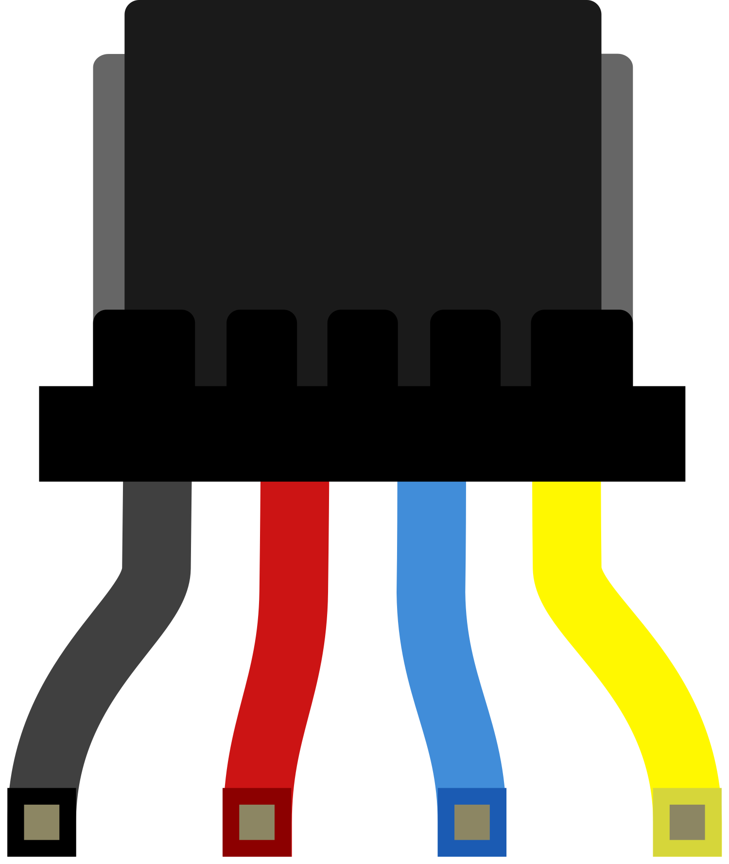
  • Connector Type: 1mm pitch, 4-pin JST connector on one end, and male breadboard jumper leads on the other.
  • Cable Length: Typically ranges from 100mm to 200mm, but may vary by manufacturer.
  • Wire Gauge: 28 AWG.
  • Voltage Rating: Typically 3.3V to 5V, conforming to standard Qwiic system requirements.
  • Current Rating: Up to 1A, but this may vary based on wire gauge and insulation material.

Pin Configuration and Descriptions

Pin Number Qwiic Connector Breadboard Jumper Color Description
1 SDA Blue Serial Data Line
2 SCL Yellow Serial Clock Line
3 VCC Red Power Supply Voltage
4 GND Black Ground

Usage Instructions

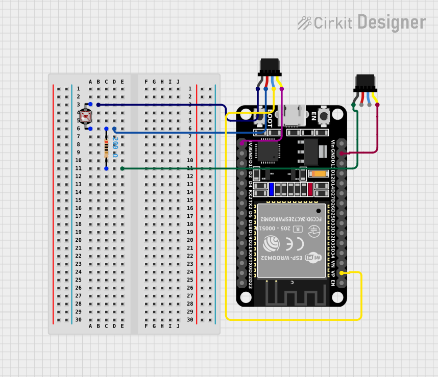
Connecting to a Breadboard

  1. Identify the Pins: Refer to the pin configuration table above to identify the SDA, SCL, VCC, and GND leads.
  2. Insert into Breadboard: Insert the male jumper leads into the breadboard, ensuring that each pin is connected to the correct breadboard row.
  3. Connect to Qwiic Device: Attach the Qwiic connector to your Qwiic-enabled device, ensuring a firm connection.

Best Practices

  • Power Considerations: Ensure that the power supply voltage (VCC) matches the requirements of your Qwiic-enabled device.
  • Signal Integrity: Keep the cable length as short as possible to maintain signal integrity, especially for I2C high-speed communication.
  • Avoid Force: Do not apply excessive force when connecting or disconnecting the Qwiic connector to prevent damage.

Troubleshooting and FAQs

Common Issues

  • Loose Connections: If the device is not functioning, check that all connections are secure and correctly inserted into the breadboard and Qwiic device.
  • Incorrect Wiring: Double-check that the SDA and SCL lines are not swapped and that VCC and GND are correctly connected.

FAQs

Q: Can I use the Qwiic Cable with a 5V system? A: Yes, the Qwiic system is typically 3.3V, but the cables are usually 5V tolerant. However, always check the specifications of your specific Qwiic-enabled device.

Q: How do I extend the length of my Qwiic connection? A: You can use multiple Qwiic cables connected in series, but be aware that extending the length too much may affect I2C communication quality.

Q: Is it possible to connect multiple Qwiic devices using one cable? A: No, the Qwiic Cable - Breadboard Jumper is designed for a one-to-one connection. For multiple devices, use a Qwiic hub or daisy-chain compatible devices.

Example Arduino Code

Below is an example of how to initialize an I2C communication with a Qwiic-enabled device using an Arduino UNO. This is a generic setup and may vary depending on the specific device.

#include <Wire.h>

void setup() {
  Wire.begin(); // Join the I2C bus as a master
  Serial.begin(9600); // Start serial communication at 9600 baud rate
}

void loop() {
  // Your device-specific communication code here
}

Remember to consult the datasheet of your specific Qwiic-enabled device for the correct I2C addresses and commands.