How to Use UART: Examples, Pinouts, and Specs
Introduction
The Universal Asynchronous Receiver-Transmitter (UART) is a hardware communication protocol that facilitates asynchronous serial communication between devices. It is widely used in embedded systems to enable data exchange over a single wire by converting parallel data from a microcontroller into a serial format for transmission and vice versa. UART is a cornerstone of serial communication, offering simplicity and reliability in data transfer.
Explore Projects Built with UART
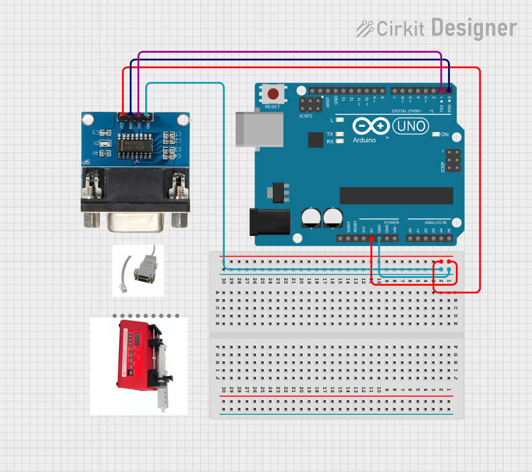

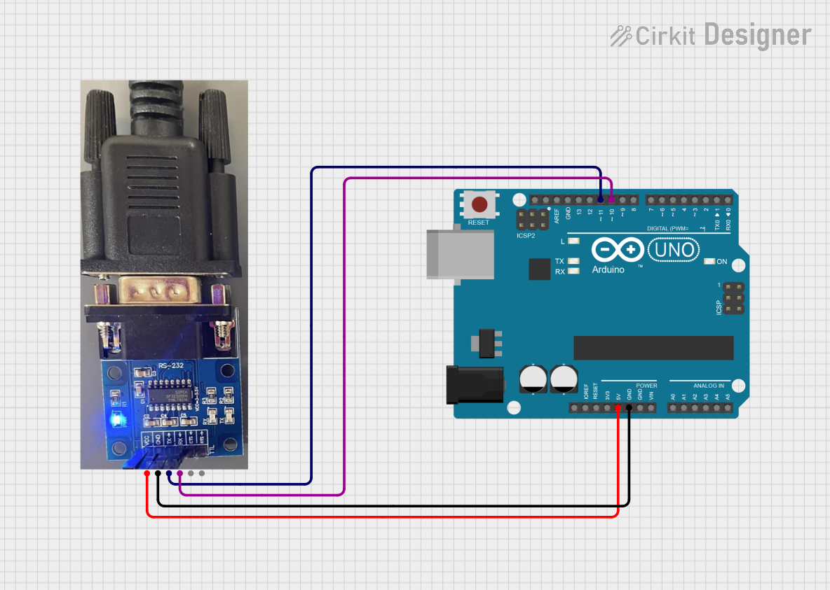
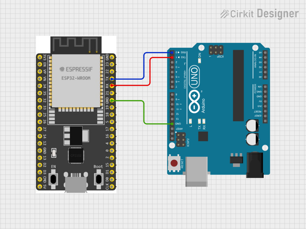
Explore Projects Built with UART
Common Applications and Use Cases
- Communication between microcontrollers and peripheral devices (e.g., sensors, displays).
- Data exchange between computers and embedded systems.
- Debugging and logging in embedded systems.
- Wireless communication modules (e.g., Bluetooth, Wi-Fi, GSM modules).
- Industrial automation and control systems.
Technical Specifications
Key Technical Details
- Communication Type: Asynchronous serial communication.
- Baud Rate: Configurable (common rates: 9600, 115200, etc.).
- Data Bits: Typically 8 bits (configurable to 5, 6, 7, or 9 bits).
- Parity: None, Even, or Odd (optional).
- Stop Bits: 1 or 2.
- Flow Control: None, RTS/CTS (hardware), or XON/XOFF (software).
- Voltage Levels:
- TTL (0V to 5V or 0V to 3.3V) for microcontrollers.
- RS-232 (-12V to +12V) for PC communication.
Pin Configuration and Descriptions
UART typically uses two main pins for communication:
| Pin Name | Description |
|---|---|
| TX (Transmit) | Sends serial data to the receiving device. |
| RX (Receive) | Receives serial data from the transmitting device. |
Optional pins for hardware flow control (if supported):
| Pin Name | Description |
|---|---|
| RTS (Request to Send) | Indicates the device is ready to send data. |
| CTS (Clear to Send) | Indicates the device is ready to receive data. |
Usage Instructions
How to Use UART in a Circuit
- Connect TX and RX Pins:
- Connect the TX pin of the transmitting device to the RX pin of the receiving device.
- Connect the RX pin of the transmitting device to the TX pin of the receiving device.
- Set the Baud Rate:
- Ensure both devices are configured to use the same baud rate for proper communication.
- Voltage Level Matching:
- Ensure the voltage levels of the UART pins match between devices (e.g., 3.3V or 5V).
- Use a level shifter if the devices operate at different voltage levels.
- Optional Flow Control:
- If using hardware flow control, connect RTS and CTS pins between devices.
Important Considerations and Best Practices
- Baud Rate Mismatch: Ensure both devices use the same baud rate, data bits, parity, and stop bits.
- Cable Length: Keep the cable length short to avoid signal degradation, especially at higher baud rates.
- Noise and Interference: Use shielded cables or twisted pairs to minimize noise in noisy environments.
- Debugging: Use a USB-to-UART converter to monitor communication on a PC.
Example: Using UART with Arduino UNO
Below is an example of how to use UART to send and receive data between an Arduino UNO and a serial terminal.
// Example: UART communication on Arduino UNO
// This code sends "Hello, UART!" to the serial terminal and echoes received data.

void setup() {
  Serial.begin(9600); // Initialize UART with a baud rate of 9600
  while (!Serial) {
    // Wait for the serial port to connect (useful for native USB boards)
  }
  Serial.println("UART Communication Initialized"); // Send initialization message
}

void loop() {
  if (Serial.available() > 0) {
    // Check if data is available to read
    char receivedChar = Serial.read(); // Read the incoming character
    Serial.print("Received: ");        // Print a label for the received data
    Serial.println(receivedChar);      // Echo the received character
  }
  delay(100); // Small delay to avoid overwhelming the serial terminal
}
Troubleshooting and FAQs
Common Issues and Solutions
No Data Transmission:
- Cause: TX and RX pins are not connected correctly.
- Solution: Verify that the TX pin of one device is connected to the RX pin of the other device.
Garbled or Corrupted Data:
- Cause: Baud rate mismatch between devices.
- Solution: Ensure both devices are configured with the same baud rate and other UART settings.
No Response from Device:
- Cause: Voltage level mismatch between devices.
- Solution: Use a level shifter to match voltage levels.
Data Loss:
- Cause: Buffer overflow due to high data rates or insufficient processing speed.
- Solution: Use hardware flow control (RTS/CTS) or reduce the baud rate.
FAQs
Can UART communicate with multiple devices?
- No, UART is designed for point-to-point communication. For multiple devices, consider using protocols like I2C or SPI.
What is the maximum baud rate for UART?
- The maximum baud rate depends on the hardware and cable length. Common microcontrollers support up to 1 Mbps or higher.
Can I use UART for long-distance communication?
- UART is not ideal for long distances due to signal degradation. Use RS-485 or similar protocols for longer distances.
How do I monitor UART communication?
- Use a USB-to-UART converter and a serial terminal application (e.g., PuTTY, Tera Term) on a PC to monitor data.
By following this documentation, you can effectively use UART for reliable serial communication in your projects.