How to Use 4 Channel Optoisolator: Examples, Pinouts, and Specs
Introduction
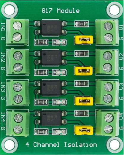
A 4 Channel Optoisolator is a device that uses light to transfer electrical signals between two isolated circuits. It provides electrical isolation, ensuring that high voltages or electrical noise in one circuit do not affect the other. This makes it an essential component for protecting sensitive electronics and ensuring reliable operation in noisy environments.
Explore Projects Built with 4 Channel Optoisolator


Explore Projects Built with 4 Channel Optoisolator
Common Applications and Use Cases
- Isolation between high-voltage and low-voltage circuits
- Signal level shifting
- Noise suppression in industrial environments
- Microcontroller interfacing with high-power devices
- Protection of sensitive components in motor control systems
Technical Specifications
Below are the key technical details for a typical 4 Channel Optoisolator:
| Parameter | Value |
|---|---|
| Number of Channels | 4 |
| Input Voltage (LED side) | 1.2V to 1.4V (typical forward voltage) |
| Input Current | 10mA to 20mA (per channel) |
| Output Voltage | Up to 30V (depending on model) |
| Isolation Voltage | 2500V to 5000V (varies by model) |
| Response Time | 2µs to 20µs (typical) |
| Operating Temperature | -40°C to +85°C |
Pin Configuration and Descriptions
The 4 Channel Optoisolator typically comes in an 8-pin or 16-pin DIP or SMD package. Below is the pin configuration for a common 16-pin DIP package:
| Pin Number | Name | Description |
|---|---|---|
| 1, 3, 5, 7 | Anode (Input) | Positive terminal for the input LEDs (channels 1-4). |
| 2, 4, 6, 8 | Cathode (Input) | Negative terminal for the input LEDs (channels 1-4). |
| 9, 11, 13, 15 | Emitter (Output) | Output terminal for the phototransistor (channels 1-4). |
| 10, 12, 14, 16 | Collector (Output) | Output terminal for the phototransistor (channels 1-4). |
Usage Instructions
How to Use the Component in a Circuit
Connect the Input Side (LED):
- Use a current-limiting resistor in series with the LED input to prevent overcurrent. Calculate the resistor value using Ohm's Law:
[ R = \frac{V_{in} - V_f}{I_f} ]
Where (V_{in}) is the input voltage, (V_f) is the forward voltage of the LED (typically 1.2V), and (I_f) is the desired forward current (e.g., 10mA).
- Use a current-limiting resistor in series with the LED input to prevent overcurrent. Calculate the resistor value using Ohm's Law:
Connect the Output Side (Phototransistor):
- The phototransistor output can be connected in either a common-emitter or common-collector configuration, depending on the application.
- Use a pull-up resistor on the collector side if the output is used as a digital signal.
Power Isolation:
- Ensure that the input and output circuits are powered by separate, isolated power supplies to maintain proper isolation.
Important Considerations and Best Practices
- Input Current: Do not exceed the maximum input current rating for the LEDs to avoid damage.
- Isolation Voltage: Ensure the voltage difference between the input and output does not exceed the isolation voltage rating.
- Response Time: For high-speed applications, choose an optoisolator with a low response time.
- Temperature: Operate the component within the specified temperature range to ensure reliability.
Example: Connecting to an Arduino UNO
Below is an example of how to use a 4 Channel Optoisolator to interface an Arduino UNO with a high-voltage circuit:
Circuit Description
- The input side of the optoisolator is connected to the Arduino's digital pins.
- The output side controls a high-voltage relay.
Code Example
// Example code for using a 4 Channel Optoisolator with Arduino UNO
// This code toggles the optoisolator inputs to control external devices.

const int optoInput1 = 2; // Arduino pin connected to optoisolator channel 1
const int optoInput2 = 3; // Arduino pin connected to optoisolator channel 2

void setup() {
  pinMode(optoInput1, OUTPUT); // Set pin as output
  pinMode(optoInput2, OUTPUT); // Set pin as output
}

void loop() {
  digitalWrite(optoInput1, HIGH); // Turn on channel 1
  delay(1000);                   // Wait for 1 second
  digitalWrite(optoInput1, LOW);  // Turn off channel 1
  delay(1000);                   // Wait for 1 second

  digitalWrite(optoInput2, HIGH); // Turn on channel 2
  delay(1000);                   // Wait for 1 second
  digitalWrite(optoInput2, LOW);  // Turn off channel 2
  delay(1000);                   // Wait for 1 second
}
Troubleshooting and FAQs
Common Issues and Solutions
LED Not Lighting Up:
- Cause: Insufficient input current or incorrect resistor value.
- Solution: Verify the resistor value and ensure the input voltage is sufficient.
No Output Signal:
- Cause: Incorrect wiring on the output side or missing pull-up resistor.
- Solution: Check the output circuit and add a pull-up resistor if needed.
Signal Distortion or Noise:
- Cause: High-speed signals or long wires causing interference.
- Solution: Use shorter wires and consider adding decoupling capacitors.
Component Overheating:
- Cause: Exceeding the maximum current or voltage ratings.
- Solution: Ensure all parameters are within the specified limits.
FAQs
Q: Can I use the 4 Channel Optoisolator for analog signals?
A: While optoisolators are primarily designed for digital signals, they can transmit analog signals with limited accuracy. For better performance, use linear optoisolators.
Q: How do I calculate the pull-up resistor value for the output?
A: The pull-up resistor value depends on the desired output current and voltage. A typical value is 10kΩ for most applications.
Q: Can I use the optoisolator for bidirectional communication?
A: No, standard optoisolators are unidirectional. For bidirectional communication, consider using specialized isolators like digital isolators.
This concludes the documentation for the 4 Channel Optoisolator.