
How to Use Arduino Fio (Funnel I/O): Examples, Pinouts, and Specs
 Design with Arduino Fio (Funnel I/O) in Cirkit Designer
Introduction
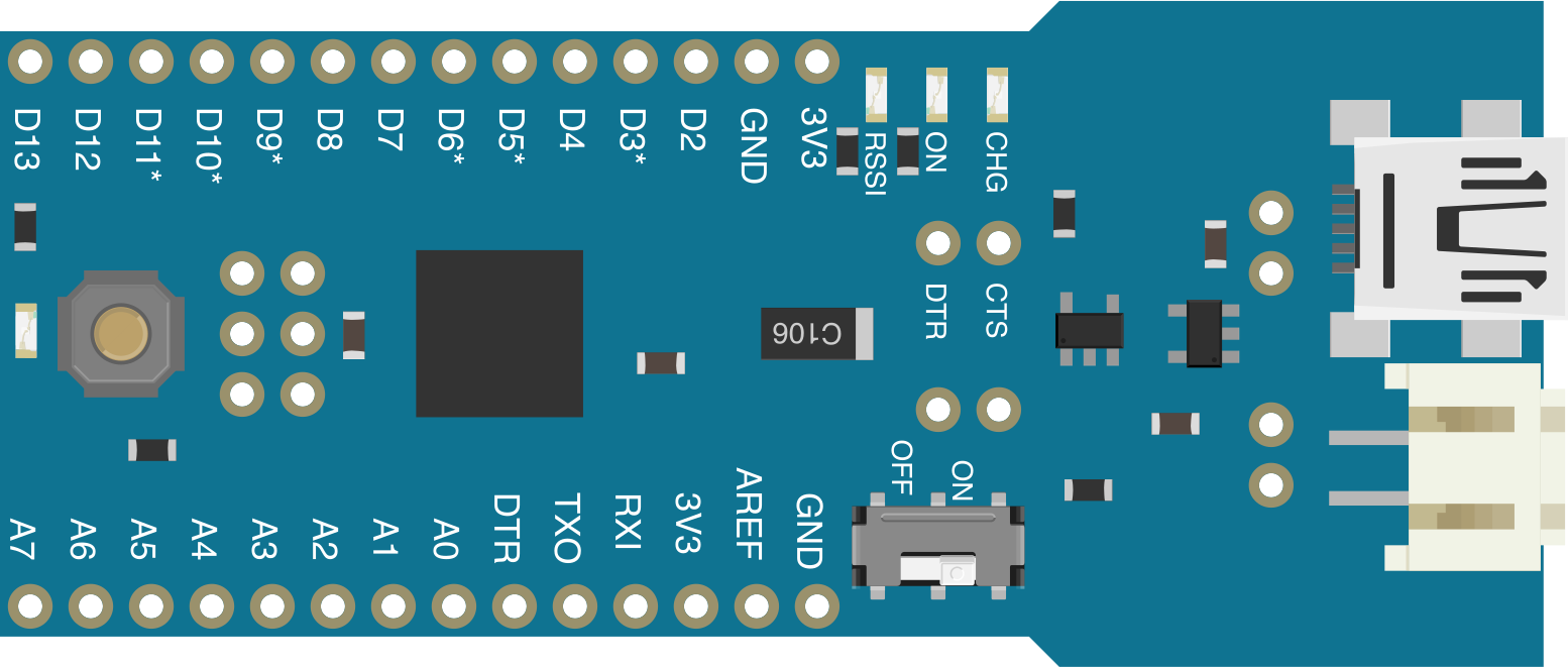
The Arduino Fio (Funnel I/O), manufactured by SparkFun Electronics (Part ID: DEV-10116), is a compact microcontroller board designed for wireless applications. It features a small form factor and is optimized for low-power projects. The Fio is particularly well-suited for projects requiring wireless communication, such as remote sensing, data logging, and wearable devices. It supports integration with XBee modules for seamless wireless connectivity and is compatible with various sensors and modules.
Explore Projects Built with Arduino Fio (Funnel I/O)
 Open Project in Cirkit Designer
 Open Project in Cirkit Designer
 Open Project in Cirkit Designer
 Open Project in Cirkit Designer
Explore Projects Built with Arduino Fio (Funnel I/O)
Open Project in Cirkit DesignerOpen Project in Cirkit DesignerOpen Project in Cirkit DesignerOpen Project in Cirkit DesignerCommon Applications
- Wireless sensor networks
- Remote data logging
- Wearable electronics
- IoT (Internet of Things) devices
- Battery-powered projects
Technical Specifications
The Arduino Fio is based on the ATmega328P microcontroller and includes features tailored for wireless and low-power applications.
Key Technical Details
| Parameter | Specification |
|---|---|
| Microcontroller | ATmega328P |
| Operating Voltage | 3.3V |
| Input Voltage (via USB) | 5V |
| Input Voltage (via JST) | 3.35V - 12V |
| Digital I/O Pins | 14 (6 PWM outputs) |
| Analog Input Pins | 8 |
| Flash Memory | 32 KB (2 KB used by bootloader) |
| SRAM | 2 KB |
| EEPROM | 1 KB |
| Clock Speed | 8 MHz |
| Wireless Support | XBee socket for wireless modules |
| Battery Connector | JST connector for LiPo batteries |
| Dimensions | 60 mm x 25 mm |
Pin Configuration and Descriptions
The Arduino Fio has a standard pinout, with additional features for wireless and battery-powered applications.
Digital Pins
| Pin Number | Function | Description |
|---|---|---|
| D0 - D7 | Digital I/O | General-purpose digital input/output pins |
| D3, D5, D6, D9, D10, D11 | PWM Output | Pulse-width modulation for motor control, LEDs, etc. |
Analog Pins
| Pin Number | Function | Description |
|---|---|---|
| A0 - A7 | Analog Input | Read analog signals (0-3.3V) |
Power Pins
| Pin Name | Function | Description |
|---|---|---|
| VIN | Input Voltage | External power input (3.35V - 12V) |
| 3.3V | Regulated Output Voltage | Provides 3.3V for external components |
| GND | Ground | Common ground for the circuit |
Special Pins
| Pin Name | Function | Description |
|---|---|---|
| RST | Reset | Resets the microcontroller |
| XBee TX/RX | Wireless Communication | Dedicated pins for XBee module communication |
Usage Instructions
How to Use the Arduino Fio in a Circuit
Powering the Board:
- Connect a LiPo battery to the JST connector for portable applications.
- Alternatively, supply power via the VIN pin (3.35V - 12V) or USB connection.
Programming the Board:
- The Arduino Fio does not have a built-in USB-to-serial converter. Use an external FTDI Basic Breakout board to upload code.
- Connect the FTDI board to the 6-pin header on the Fio, ensuring proper orientation.
Wireless Communication:
- Insert an XBee module into the onboard socket for wireless communication.
- Configure the XBee module using appropriate software (e.g., XCTU).
Connecting Sensors and Modules:
- Use the digital and analog pins to interface with sensors, actuators, and other modules.
- Ensure that connected components operate at 3.3V to avoid damage.
Important Considerations
- Voltage Levels: The Arduino Fio operates at 3.3V. Avoid connecting 5V components directly to the pins.
- Battery Charging: The onboard charging circuit allows you to charge a connected LiPo battery via USB.
- XBee Configuration: Ensure the XBee module is properly configured for your application before use.
Example Code for Arduino Fio with an XBee Module
The following example demonstrates how to send data wirelessly using an XBee module.
// Example: Sending data wirelessly using Arduino Fio and XBee
void setup() {
  Serial.begin(9600); // Initialize serial communication at 9600 baud
}

void loop() {
  Serial.println("Hello, XBee!"); // Send a message to the XBee module
  delay(1000); // Wait for 1 second before sending the next message
}
Troubleshooting and FAQs
Common Issues and Solutions
Problem: The board does not power on.
Solution:- Check the battery connection and ensure it is properly seated in the JST connector.
- Verify that the input voltage is within the acceptable range (3.35V - 12V).
Problem: Unable to upload code to the board.
Solution:- Ensure the FTDI Basic Breakout board is connected correctly to the 6-pin header.
- Verify that the correct COM port and board type are selected in the Arduino IDE.
Problem: XBee module is not communicating.
Solution:- Check the XBee module's configuration using XCTU software.
- Ensure the module is securely seated in the socket.
Problem: Connected components are not functioning correctly.
Solution:- Verify that all components are compatible with the 3.3V operating voltage.
- Double-check wiring and connections.
FAQs
Q: Can I use the Arduino Fio with 5V sensors?
A: No, the Arduino Fio operates at 3.3V. Use a level shifter or voltage divider to interface with 5V sensors.
Q: How do I charge the LiPo battery?
A: Connect the Arduino Fio to a USB power source. The onboard charging circuit will handle the charging process.
Q: Can I use the Arduino Fio without an XBee module?
A: Yes, the Fio can function as a standalone microcontroller board without an XBee module.
Q: What is the maximum range of the XBee module?
A: The range depends on the specific XBee module used. Refer to the XBee module's datasheet for details.
This concludes the documentation for the Arduino Fio (Funnel I/O). For further assistance, refer to the official SparkFun Electronics resources.