Cirkit Designer Logo
Cirkit Designer
Your all-in-one circuit design IDE
Home / 
Component Documentation

How to Use ST7735 128x128 1.44 TFT I2C Color: Examples, Pinouts, and Specs

Image of ST7735 128x128 1.44 TFT I2C Color
Cirkit Designer LogoDesign with ST7735 128x128 1.44 TFT I2C Color in Cirkit Designer

Introduction

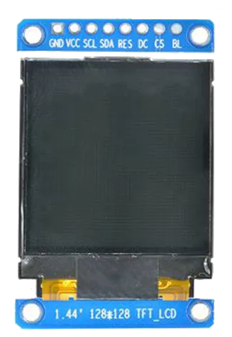
The ST7735 128x128 1.44" TFT I2C Color Display is a compact and versatile display module capable of rendering colorful graphics and text. It is widely used in embedded systems, handheld devices, and user interfaces where space is at a premium. With its I2C communication protocol, it simplifies the connectivity and reduces the pin usage on microcontrollers, such as the Arduino UNO.

Explore Projects Built with ST7735 128x128 1.44 TFT I2C Color

Use Cirkit Designer to design, explore, and prototype these projects online. Some projects support real-time simulation. Click "Open Project" to start designing instantly!
Arduino Nano Controlled TFT Display with Multiple Pushbuttons
Image of rey: A project utilizing ST7735 128x128 1.44 TFT I2C Color in a practical application
This circuit features an Arduino Nano microcontroller connected to a ST7735 128x128 1.44 TFT I2C Color display and multiple pushbuttons. The display is interfaced with the Arduino via digital pins for control signals and SPI pins for data transfer. The pushbuttons are connected to various digital and analog input pins on the Arduino, likely intended for user input to control the display or other functions within the code.
Cirkit Designer LogoOpen Project in Cirkit Designer
Arduino-Based RGB Color Detection System with OLED and LCD Displays
Image of 1: A project utilizing ST7735 128x128 1.44 TFT I2C Color in a practical application
This circuit uses an Arduino UNO to interface with an Adafruit TCS34725 RGB color sensor, a 128x64 OLED display, and a 16x2 I2C LCD. The Arduino reads color data from the sensor and displays the color information on both the OLED and LCD screens.
Cirkit Designer LogoOpen Project in Cirkit Designer
Arduino UNO Controlled TCS3200 Color Sensor with I2C LCD Display
Image of CeledonioT3: A project utilizing ST7735 128x128 1.44 TFT I2C Color in a practical application
This circuit features an Arduino UNO microcontroller interfaced with a TCS3200 color sensor and an I2C LCD 16x2 display. The TCS3200 color sensor's output is connected to the Arduino's digital pin D12, and its frequency scaling pins (S0-S3) are connected to digital pins D8-D11 for configuration. The LCD display communicates with the Arduino via the I2C protocol, using A4 (SDA) and A5 (SCL) for data transfer, allowing the system to display color readings or other information from the sensor.
Cirkit Designer LogoOpen Project in Cirkit Designer
Arduino 101 Based Color Sensing Display with Buzzer Notification
Image of ADC Lab 10: A project utilizing ST7735 128x128 1.44 TFT I2C Color in a practical application
This circuit features an Arduino 101 microcontroller connected to a TCS3200 color sensor and a 16x2 I2C LCD display for output. The Arduino is configured to communicate with the LCD via I2C (using A4/SDA and A5/SCL pins for data exchange) and to receive color frequency signals from the TCS3200 on its D6 PWM pin. Additionally, a buzzer is connected to the D8 pin of the Arduino, potentially for audio signaling based on color detection or other programmed conditions.
Cirkit Designer LogoOpen Project in Cirkit Designer

Explore Projects Built with ST7735 128x128 1.44 TFT I2C Color

Use Cirkit Designer to design, explore, and prototype these projects online. Some projects support real-time simulation. Click "Open Project" to start designing instantly!
Image of rey: A project utilizing ST7735 128x128 1.44 TFT I2C Color in a practical application
Arduino Nano Controlled TFT Display with Multiple Pushbuttons
This circuit features an Arduino Nano microcontroller connected to a ST7735 128x128 1.44 TFT I2C Color display and multiple pushbuttons. The display is interfaced with the Arduino via digital pins for control signals and SPI pins for data transfer. The pushbuttons are connected to various digital and analog input pins on the Arduino, likely intended for user input to control the display or other functions within the code.
Cirkit Designer LogoOpen Project in Cirkit Designer
Image of 1: A project utilizing ST7735 128x128 1.44 TFT I2C Color in a practical application
Arduino-Based RGB Color Detection System with OLED and LCD Displays
This circuit uses an Arduino UNO to interface with an Adafruit TCS34725 RGB color sensor, a 128x64 OLED display, and a 16x2 I2C LCD. The Arduino reads color data from the sensor and displays the color information on both the OLED and LCD screens.
Cirkit Designer LogoOpen Project in Cirkit Designer
Image of CeledonioT3: A project utilizing ST7735 128x128 1.44 TFT I2C Color in a practical application
Arduino UNO Controlled TCS3200 Color Sensor with I2C LCD Display
This circuit features an Arduino UNO microcontroller interfaced with a TCS3200 color sensor and an I2C LCD 16x2 display. The TCS3200 color sensor's output is connected to the Arduino's digital pin D12, and its frequency scaling pins (S0-S3) are connected to digital pins D8-D11 for configuration. The LCD display communicates with the Arduino via the I2C protocol, using A4 (SDA) and A5 (SCL) for data transfer, allowing the system to display color readings or other information from the sensor.
Cirkit Designer LogoOpen Project in Cirkit Designer
Image of ADC Lab 10: A project utilizing ST7735 128x128 1.44 TFT I2C Color in a practical application
Arduino 101 Based Color Sensing Display with Buzzer Notification
This circuit features an Arduino 101 microcontroller connected to a TCS3200 color sensor and a 16x2 I2C LCD display for output. The Arduino is configured to communicate with the LCD via I2C (using A4/SDA and A5/SCL pins for data exchange) and to receive color frequency signals from the TCS3200 on its D6 PWM pin. Additionally, a buzzer is connected to the D8 pin of the Arduino, potentially for audio signaling based on color detection or other programmed conditions.
Cirkit Designer LogoOpen Project in Cirkit Designer

Common Applications and Use Cases

  • Portable instruments
  • Wearable devices
  • Home automation interfaces
  • DIY electronics projects
  • Educational and hobbyist projects

Technical Specifications

Key Technical Details

  • Display Size: 1.44 inches
  • Resolution: 128x128 pixels
  • Interface: I2C (Inter-Integrated Circuit)
  • Color Depth: 16-bit (65K colors)
  • Operating Voltage: 3.3V - 5V
  • Logic Level: 3.3V (5V tolerant)

Pin Configuration and Descriptions

Pin Number Pin Name Description
1 VCC Power supply (3.3V - 5V)
2 GND Ground
3 SCL I2C clock signal
4 SDA I2C data signal
5 RES Reset pin (active low)
6 DC Data/Command control pin
7 CS Chip Select (active low, optional)
8 BL Backlight control (optional)

Usage Instructions

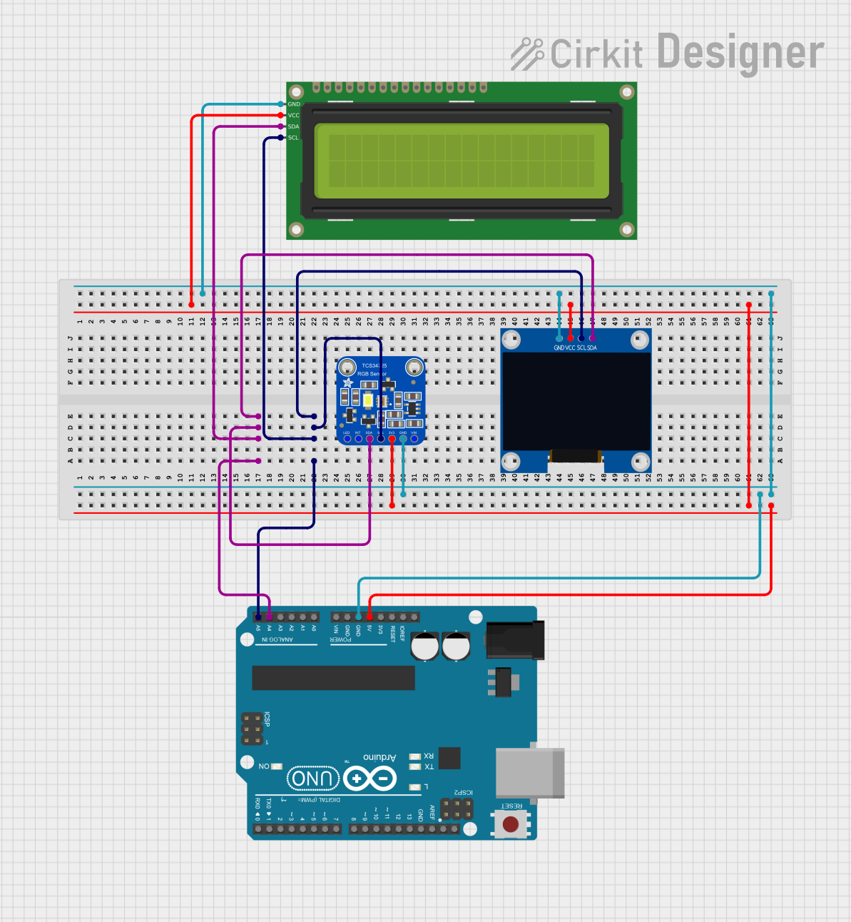
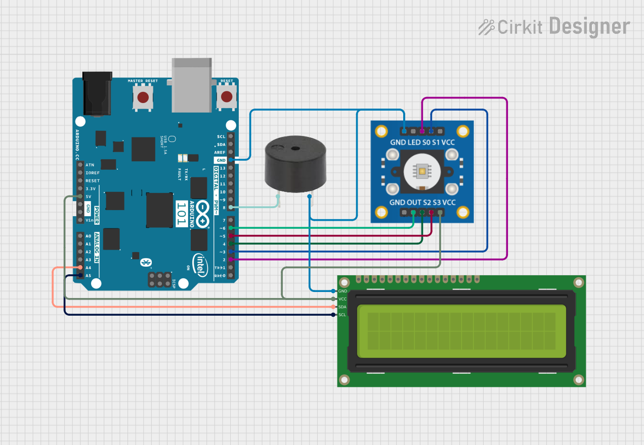
How to Use the Component in a Circuit

  1. Connect the VCC pin to the power supply (3.3V or 5V).
  2. Connect the GND pin to the ground of the power supply.
  3. Connect the SCL and SDA pins to the I2C clock and data lines on the microcontroller.
  4. The RES pin should be connected to a digital output pin for resetting the display.
  5. The DC pin is used to switch between data and command modes and should be connected to another digital output pin.
  6. If used, the CS pin can be connected to a digital output pin for enabling the display.
  7. The BL pin controls the backlight and can be connected to a PWM output for brightness control or directly to VCC for full brightness.

Important Considerations and Best Practices

  • Ensure that the power supply voltage is within the specified range to prevent damage.
  • Use pull-up resistors on the I2C lines if they are not included on the microcontroller board.
  • When using a 5V microcontroller, ensure that the logic level is compatible or use a level shifter.
  • Avoid exposing the display to direct sunlight or high temperatures to prevent damage.
  • Handle the display with care to avoid physical damage to the screen.

Example Code for Arduino UNO

#include <Wire.h> // Include Wire library for I2C communication
#include <Adafruit_GFX.h> // Include core graphics library
#include <Adafruit_ST7735.h> // Include hardware-specific library for ST7735

// Define pin connections
#define TFT_CS     10 // Chip select line for TFT display
#define TFT_RST    9  // Reset line for TFT (or connect to +5V)
#define TFT_DC     8  // Data/command line for TFT

// Create display object
Adafruit_ST7735 tft = Adafruit_ST7735(TFT_CS, TFT_DC, TFT_RST);

void setup() {
  tft.initR(INITR_144GREENTAB); // Initialize display with correct tab color
  tft.fillScreen(ST7735_BLACK);  // Clear screen with black background
}

void loop() {
  tft.setCursor(0, 0);           // Set cursor at top-left corner
  tft.setTextColor(ST7735_WHITE); // Set text color to white
  tft.setTextWrap(true);          // Set text to wrap at end of screen
  tft.print("Hello, World!");     // Print text to screen
}

Troubleshooting and FAQs

Common Issues Users Might Face

  • Display not powering on: Check the connections to VCC and GND, and ensure the power supply is within the specified voltage range.
  • No display or corrupted image: Verify that the I2C lines are connected correctly and that the correct I2C address is being used in the code.
  • Dim or no backlight: Ensure the BL pin is connected properly and receiving power. If connected to a PWM pin, check the PWM signal.

Solutions and Tips for Troubleshooting

  • Double-check all wiring against the pin configuration table.
  • Use a multimeter to verify that the power supply is delivering the correct voltage.
  • If using an Arduino UNO, ensure that the library examples are correctly modified for the ST7735 display.
  • Consult the display's datasheet for detailed timing and initialization information.

FAQs

Q: Can I use this display with a 5V microcontroller? A: Yes, but ensure that the logic levels are compatible or use a level shifter.

Q: How can I control the brightness of the backlight? A: Connect the BL pin to a PWM-capable pin on your microcontroller and adjust the duty cycle to control brightness.

Q: What library should I use with this display? A: The Adafruit ST7735 library is recommended for easy integration and use with Arduino platforms.

Q: How do I update the display content? A: Use the functions provided by the Adafruit GFX and ST7735 libraries to draw text, shapes, and images, and then call display() to update the screen.

Q: Can I display images on the ST7735? A: Yes, you can display images by converting them to the appropriate format and using the library's image drawing functions.