How to Use SERVO DRIVER: Examples, Pinouts, and Specs
Introduction
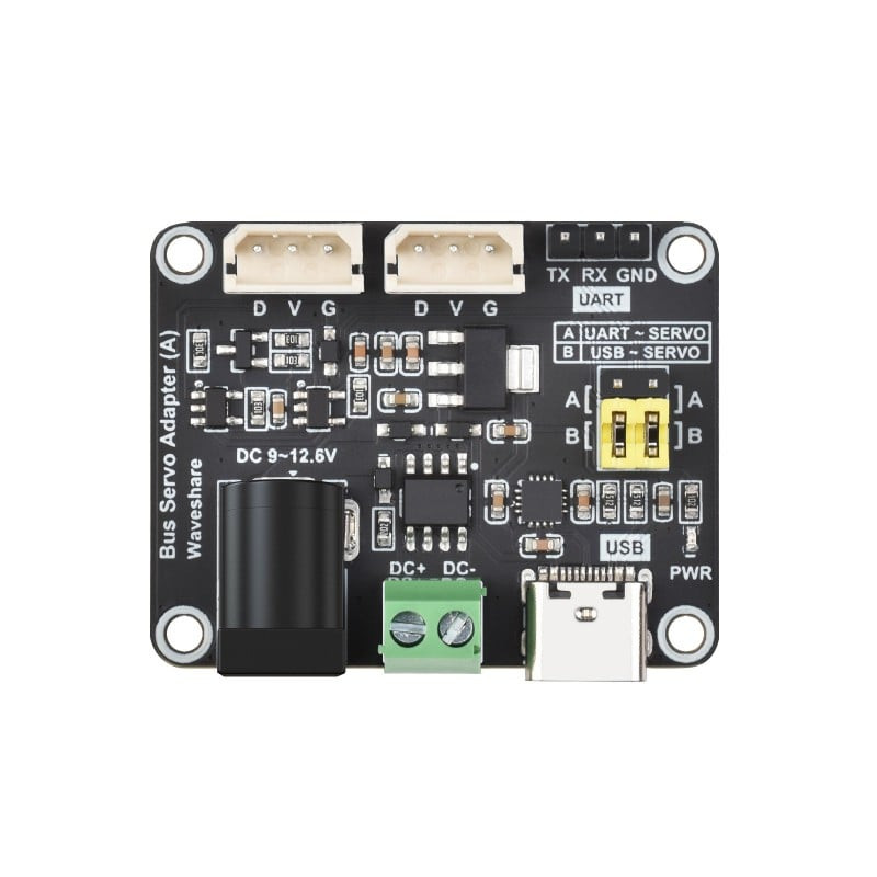
A servo driver is an electronic device designed to control the position, speed, and torque of a servo motor by sending precise signals based on input commands. The WAVESHARE Servo Driver is a versatile and reliable component that simplifies the control of servo motors in various applications. It is widely used in robotics, automation systems, RC vehicles, and other projects requiring precise motor control.
Explore Projects Built with SERVO DRIVER
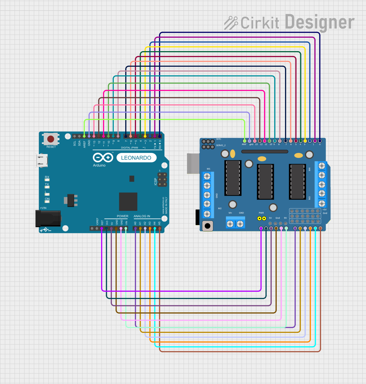
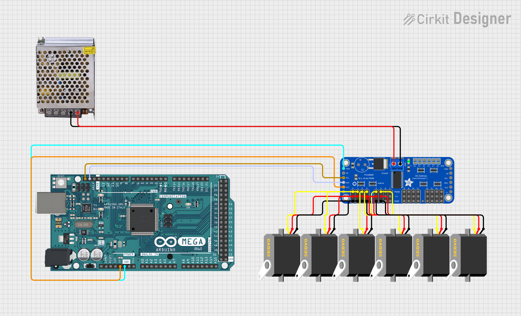
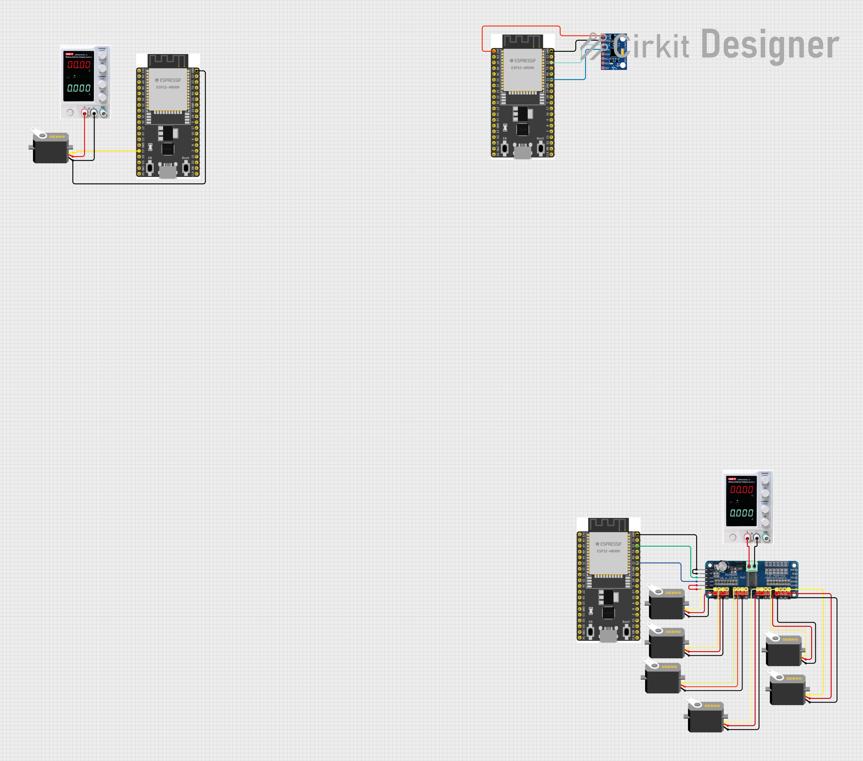
Explore Projects Built with SERVO DRIVER
Common Applications
- Robotics (e.g., robotic arms, humanoid robots)
- RC vehicles (e.g., cars, planes, boats)
- Automation systems
- Camera gimbals and pan-tilt mechanisms
- Industrial machinery requiring precise motion control
Technical Specifications
The WAVESHARE Servo Driver is designed to interface with multiple servo motors and provides stable, accurate control. Below are the key technical details:
General Specifications
- Input Voltage: 5V to 12V DC
- Control Signal Voltage: 3.3V or 5V logic compatible
- Output Channels: Supports up to 16 servo motors
- Communication Protocol: I2C (default address: 0x40)
- PWM Frequency: Adjustable from 40Hz to 1000Hz
- Resolution: 12-bit (4096 steps per PWM cycle)
- Operating Temperature: -40°C to 85°C
- Dimensions: 60mm x 25mm x 10mm
Pin Configuration
The WAVESHARE Servo Driver features a straightforward pin layout for easy integration. Below is the pin description:
| Pin Name | Type | Description |
|---|---|---|
| VCC | Power Input | Connect to a 5V-12V DC power source. |
| GND | Ground | Connect to the ground of the power supply and the microcontroller. |
| SDA | I2C Data Line | Connect to the SDA pin of the microcontroller (e.g., Arduino, Raspberry Pi). |
| SCL | I2C Clock Line | Connect to the SCL pin of the microcontroller. |
| PWM Channels | Output | 16 channels for connecting servo motors (labeled 0 to 15). |
Usage Instructions
The WAVESHARE Servo Driver is easy to use and integrates seamlessly with microcontrollers like Arduino. Follow the steps below to use the component effectively:
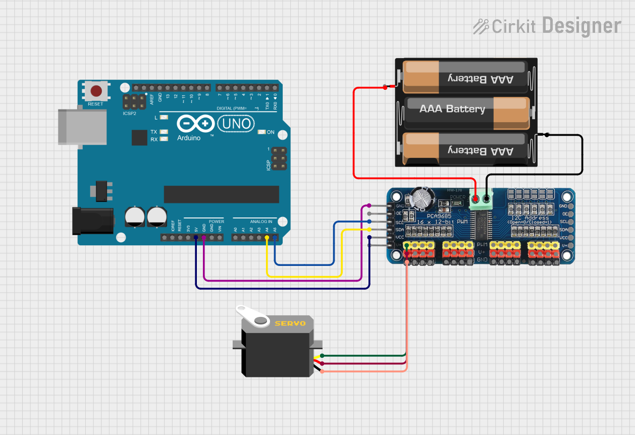
Step 1: Wiring the Servo Driver
- Power Supply: Connect the VCC pin to a 5V-12V DC power source and the GND pin to the ground.
- Microcontroller Connection: Connect the SDA and SCL pins to the corresponding I2C pins on your microcontroller.
- For Arduino UNO:
- SDA → A4
- SCL → A5
- For Arduino UNO:
- Servo Motor Connection: Connect the servo motor signal wires to the PWM output channels (0 to 15). Ensure the power and ground wires of the servo motors are connected to the driver.
Step 2: Installing Required Libraries
For Arduino, install the Adafruit PWM Servo Driver Library:
- Open the Arduino IDE.
- Go to Sketch > Include Library > Manage Libraries.
- Search for "Adafruit PWM Servo Driver" and install it.
Step 3: Example Code
Below is an example Arduino sketch to control a servo motor using the WAVESHARE Servo Driver:
#include <Wire.h>
#include <Adafruit_PWMServoDriver.h>

// Create an instance of the PWM driver
Adafruit_PWMServoDriver pwm = Adafruit_PWMServoDriver();

#define SERVO_MIN 150 // Minimum pulse length for the servo
#define SERVO_MAX 600 // Maximum pulse length for the servo

void setup() {
  Serial.begin(9600);
  Serial.println("Initializing Servo Driver...");

  // Initialize the PWM driver with the default I2C address (0x40)
  pwm.begin();
  pwm.setPWMFreq(50); // Set PWM frequency to 50Hz for servos
}

void loop() {
  // Move servo on channel 0 to minimum position
  pwm.setPWM(0, 0, SERVO_MIN);
  delay(1000); // Wait for 1 second

  // Move servo on channel 0 to maximum position
  pwm.setPWM(0, 0, SERVO_MAX);
  delay(1000); // Wait for 1 second
}
Important Considerations
- Ensure the power supply can handle the current requirements of all connected servo motors.
- Use a capacitor (e.g., 1000µF) across the VCC and GND pins to stabilize the power supply.
- Avoid exceeding the voltage and current ratings of the servo driver to prevent damage.
- If using multiple servo motors, ensure the total current draw does not exceed the power supply's capacity.
Troubleshooting and FAQs
Common Issues and Solutions
Servo Motors Not Moving
- Cause: Incorrect wiring or insufficient power supply.
- Solution: Double-check all connections and ensure the power supply meets the current requirements.
Erratic Servo Movement
- Cause: Noise or instability in the power supply.
- Solution: Add a capacitor (e.g., 1000µF) across the VCC and GND pins to filter noise.
I2C Communication Failure
- Cause: Incorrect SDA/SCL connections or address conflict.
- Solution: Verify the SDA and SCL connections. Ensure no other devices on the I2C bus share the same address (default: 0x40).
Overheating
- Cause: Excessive current draw or prolonged operation at high loads.
- Solution: Use a heat sink or fan for cooling. Reduce the load on the servo motors.
FAQs
Q1: Can I use the WAVESHARE Servo Driver with a Raspberry Pi?
Yes, the driver is compatible with Raspberry Pi. Connect the SDA and SCL pins to the corresponding GPIO pins on the Raspberry Pi (SDA → GPIO2, SCL → GPIO3).
Q2: How many servo motors can I control simultaneously?
The driver supports up to 16 servo motors, each connected to a separate PWM channel.
Q3: Can I change the I2C address of the driver?
Yes, the I2C address can be changed by soldering the address selection pads on the board. Refer to the manufacturer's datasheet for details.
Q4: What is the maximum PWM frequency supported?
The driver supports PWM frequencies up to 1000Hz, but for servo motors, a frequency of 50Hz is typically used.
By following this documentation, you can effectively use the WAVESHARE Servo Driver in your projects for precise and reliable servo motor control.