
How to Use NRF24L01 Adapter: Examples, Pinouts, and Specs
 Design with NRF24L01 Adapter in Cirkit Designer
Introduction
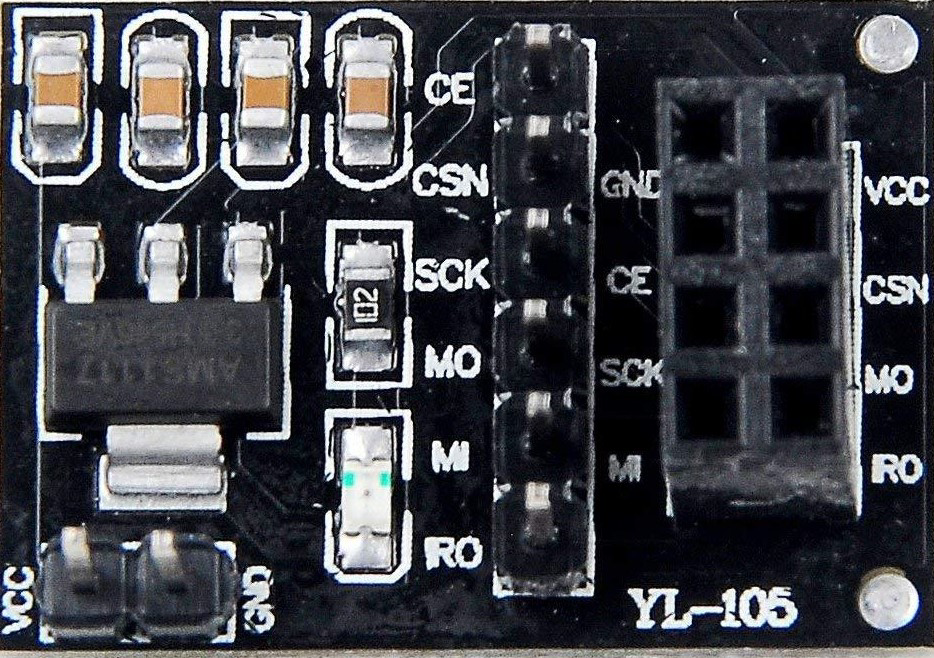
The NRF24L01 Adapter is a module designed to simplify the use of the NRF24L01 wireless transceiver. It provides an interface for seamless communication between the NRF24L01 module and microcontrollers, such as Arduino, Raspberry Pi, or other embedded systems. The adapter ensures proper voltage regulation and pin compatibility, making it easier to integrate the NRF24L01 into your projects.
Explore Projects Built with NRF24L01 Adapter
 Open Project in Cirkit Designer
 Open Project in Cirkit Designer
 Open Project in Cirkit Designer
 Open Project in Cirkit Designer
Explore Projects Built with NRF24L01 Adapter
Open Project in Cirkit DesignerOpen Project in Cirkit DesignerOpen Project in Cirkit DesignerOpen Project in Cirkit DesignerCommon Applications and Use Cases
- Wireless sensor networks
- Remote control systems (e.g., drones, RC cars)
- Home automation
- Internet of Things (IoT) devices
- Wireless data logging and monitoring
Technical Specifications
The NRF24L01 Adapter is designed to work with the NRF24L01 transceiver module and provides the necessary voltage regulation and pinout for easy interfacing.
Key Technical Details
- Input Voltage: 5V (regulated to 3.3V for NRF24L01)
- Output Voltage to NRF24L01: 3.3V
- Current Consumption: ~12mA (idle), ~250mA (transmitting at max power)
- Communication Protocol: SPI (Serial Peripheral Interface)
- Operating Frequency: 2.4 GHz ISM band
- Range: Up to 100 meters (line of sight, depending on antenna and environment)
Pin Configuration and Descriptions
The NRF24L01 Adapter typically has a 10-pin header for connecting the NRF24L01 module and a 6-pin header for interfacing with a microcontroller.
NRF24L01 Adapter to NRF24L01 Module
| Pin Name | Description |
|---|---|
| VCC | 3.3V power supply for the NRF24L01 |
| GND | Ground connection |
| CE | Chip Enable, used to activate the module |
| CSN | Chip Select Not, SPI slave select |
| SCK | Serial Clock, SPI clock signal |
| MOSI | Master Out Slave In, SPI data input |
| MISO | Master In Slave Out, SPI data output |
| IRQ | Interrupt Request, optional for advanced features |
NRF24L01 Adapter to Microcontroller
| Pin Name | Description |
|---|---|
| VCC | 5V input from the microcontroller |
| GND | Ground connection |
| CE | Connect to a GPIO pin on the microcontroller |
| CSN | Connect to a GPIO pin on the microcontroller |
| SCK | Connect to the SPI clock pin |
| MOSI | Connect to the SPI MOSI pin |
| MISO | Connect to the SPI MISO pin |
Usage Instructions
How to Use the NRF24L01 Adapter in a Circuit
- Connect the NRF24L01 Module to the Adapter:
- Align the pins of the NRF24L01 module with the adapter's 10-pin header and insert it securely.
- Connect the Adapter to the Microcontroller:
- Use jumper wires to connect the adapter's 6-pin header to the corresponding SPI pins on your microcontroller.
- Ensure the VCC pin is connected to a 5V power source, and the GND pin is connected to ground.
- Install Required Libraries:
- For Arduino, install the "RF24" library from the Arduino Library Manager.
- Write and Upload Code:
- Use the example code below to test communication between two NRF24L01 modules.
Important Considerations and Best Practices
- Power Supply: Ensure the adapter is powered with 5V. The onboard regulator will step it down to 3.3V for the NRF24L01 module.
- Antenna Placement: For optimal range, position the NRF24L01 module's antenna away from metal objects and other sources of interference.
- Capacitor Usage: Add a 10µF capacitor across the VCC and GND pins of the adapter to stabilize the power supply and prevent communication issues.
- SPI Pin Mapping: Verify the SPI pin mapping for your specific microcontroller, as it may vary.
Example Code for Arduino UNO
#include <SPI.h>
#include <nRF24L01.h>
#include <RF24.h>

// Define the CE and CSN pins for the NRF24L01 module
#define CE_PIN 9
#define CSN_PIN 10

// Create an RF24 object
RF24 radio(CE_PIN, CSN_PIN);

// Define the address for communication
const byte address[6] = "00001";

void setup() {
  Serial.begin(9600); // Initialize serial communication
  radio.begin();      // Initialize the NRF24L01 module
  radio.openWritingPipe(address); // Set the address for transmission
  radio.setPALevel(RF24_PA_LOW);  // Set power level to low
  radio.stopListening();          // Set the module to transmit mode
}

void loop() {
  const char text[] = "Hello, World!"; // Message to send
  bool success = radio.write(&text, sizeof(text)); // Send the message

  if (success) {
    Serial.println("Message sent successfully!");
  } else {
    Serial.println("Message failed to send.");
  }

  delay(1000); // Wait 1 second before sending the next message
}
Troubleshooting and FAQs
Common Issues and Solutions
No Communication Between Modules:
- Ensure both modules are using the same address and communication settings (e.g., data rate, channel).
- Check all connections for loose wires or incorrect pin mappings.
- Add a capacitor (10µF) across the VCC and GND pins to stabilize the power supply.
Short Range or Unstable Connection:
- Ensure the antenna is not obstructed or placed near sources of interference.
- Use a high-power NRF24L01 module with an external antenna for extended range.
Module Not Detected:
- Verify that the adapter is receiving 5V power and the NRF24L01 module is properly seated.
- Check the SPI connections and ensure the correct pins are defined in the code.
FAQs
Q: Can I use the NRF24L01 Adapter with a 3.3V microcontroller?
A: Yes, but you must bypass the onboard voltage regulator and connect the 3.3V supply directly to the NRF24L01 module. Ensure the microcontroller's SPI pins are also 3.3V compatible.
Q: What is the maximum range of the NRF24L01 module?
A: The range depends on the environment and antenna type. Standard modules can achieve up to 100 meters in line-of-sight conditions, while high-power modules with external antennas can reach several hundred meters.
Q: Why do I need a capacitor across VCC and GND?
A: The NRF24L01 module can draw high current during transmission, causing voltage fluctuations. A capacitor helps stabilize the power supply and prevents communication failures.