How to Use Pilot Lamp Green: Examples, Pinouts, and Specs
Introduction
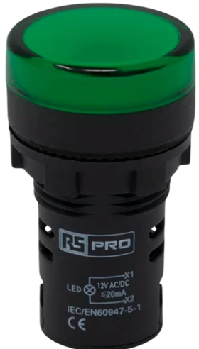
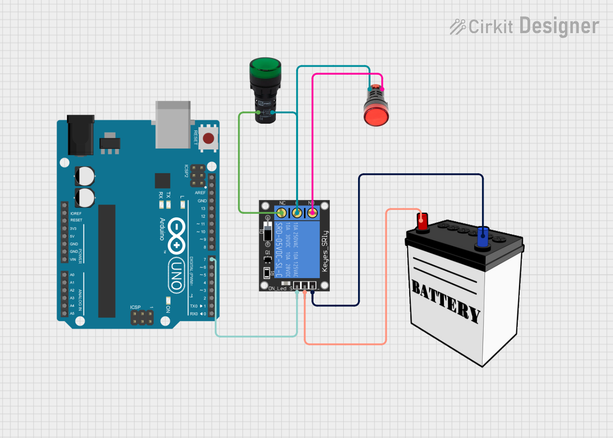
A green pilot lamp is a simple yet crucial component in various electrical and electronic systems. It serves as an indicator light that illuminates when the circuit is energized, providing a visual confirmation of the operational status. Commonly found on control panels, machinery, and household appliances, green pilot lamps are used to indicate power on, system normal, or safe conditions.
Explore Projects Built with Pilot Lamp Green
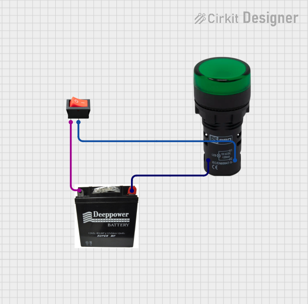
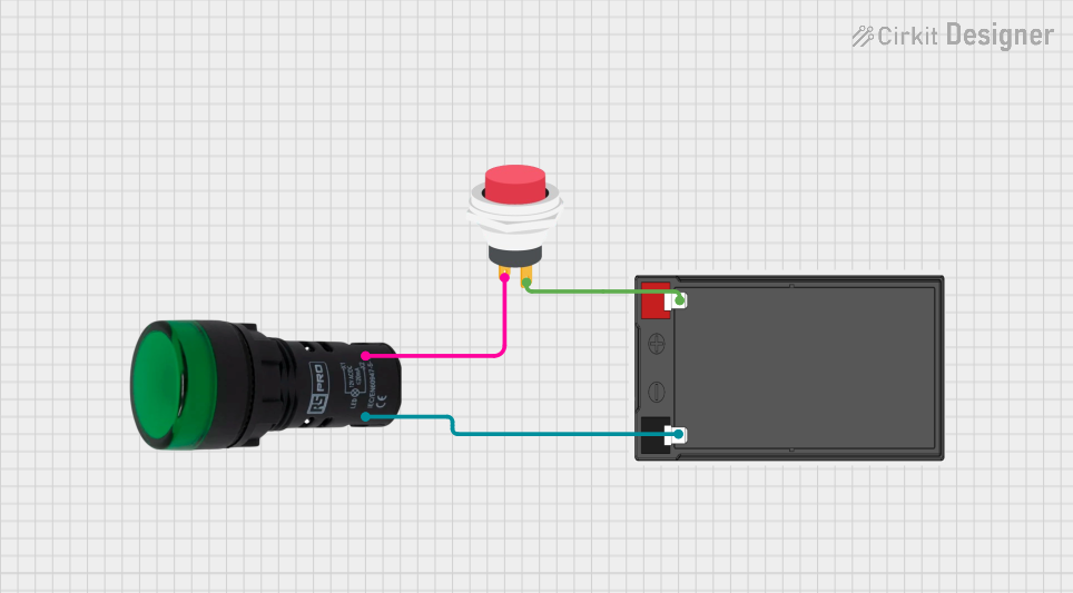
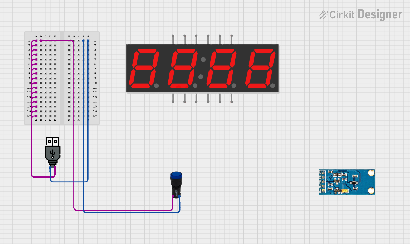
Explore Projects Built with Pilot Lamp Green
Common Applications and Use Cases
- Control panels for industrial machinery
- Power status indicator on electronic devices
- Safety assurance in electrical circuits
- Monitoring the status of critical systems
Technical Specifications
Key Technical Details
- Voltage Rating: Typically ranges from 6V to 240V
- Current Rating: Depends on the lamp type, often between 10mA to 20mA for LEDs
- Power Consumption: Low, usually less than 0.5W for LED lamps
- Lifespan: LED lamps can last up to 50,000 hours or more
- Operating Temperature: Varies with design, often between -20°C to +65°C
Pin Configuration and Descriptions
| Pin Number | Description | Notes |
|---|---|---|
| 1 | Anode (+) | Connect to positive voltage |
| 2 | Cathode (-) | Connect to ground (0V) |
Note: The pin configuration may vary depending on the specific design of the pilot lamp. Always refer to the manufacturer's datasheet for exact details.
Usage Instructions
How to Use the Component in a Circuit
- Identify the Voltage Rating: Ensure the pilot lamp's voltage rating matches the circuit voltage.
- Connect the Anode: Wire the anode pin to the point in the circuit where you want the lamp to indicate power or status.
- Connect the Cathode: Attach the cathode pin to the ground of the circuit.
- Current Limiting Resistor: If using an LED-based pilot lamp, include a current-limiting resistor in series to prevent damage.
Important Considerations and Best Practices
- Voltage Matching: Always match the lamp's voltage rating with the circuit voltage to prevent damage.
- Polarity: Observe correct polarity when connecting the lamp to prevent malfunction.
- Heat Dissipation: Ensure adequate ventilation around the lamp as it may generate heat during operation.
- Mounting: Secure the lamp firmly in place to prevent loosening due to vibration or shock.
Troubleshooting and FAQs
Common Issues Users Might Face
- Lamp Does Not Illuminate: Check for proper voltage supply and correct polarity connections.
- Flickering Lamp: Inspect for loose connections or intermittent power supply.
- Dim Lamp: Verify that the voltage level is within the specified range and that the current-limiting resistor is of the correct value.
Solutions and Tips for Troubleshooting
- Check Connections: Ensure all connections are secure and free from corrosion.
- Voltage Measurement: Use a multimeter to verify that the voltage at the lamp terminals is correct.
- Resistor Value: Recalculate the current-limiting resistor value to ensure it is suitable for the circuit voltage.
FAQs
Q: Can I use a green pilot lamp with an Arduino UNO? A: Yes, you can use a green pilot lamp with an Arduino UNO, but ensure you include a current-limiting resistor.
Q: What size of resistor do I need for a 5V circuit? A: For a typical LED pilot lamp with a forward voltage of 2V and current rating of 20mA, use a resistor value of (5V - 2V) / 20mA = 150Ω.
Q: How do I know if my pilot lamp is burnt out? A: If the lamp does not illuminate when voltage is applied and all connections are correct, the lamp may be burnt out and needs replacement.
Example Arduino UNO Code
// Define the pin where the pilot lamp is connected
const int pilotLampPin = 13; // Using the built-in LED pin for demonstration

void setup() {
  // Set the pilot lamp pin as an output
  pinMode(pilotLampPin, OUTPUT);
}

void loop() {
  // Turn on the pilot lamp
  digitalWrite(pilotLampPin, HIGH);
  // Keep the lamp on for 1 second
  delay(1000);
  // Turn off the pilot lamp
  digitalWrite(pilotLampPin, LOW);
  // Keep the lamp off for 1 second
  delay(1000);
}
Note: The above code uses the built-in LED on the Arduino UNO for demonstration purposes. When connecting an external pilot lamp, ensure it is connected through a current-limiting resistor to the specified digital pin.