Cirkit Designer Logo
Cirkit Designer
Your all-in-one circuit design IDE
Home / 
Component Documentation

How to Use TMC5160-BOB: Examples, Pinouts, and Specs

Image of TMC5160-BOB
Cirkit Designer LogoDesign with TMC5160-BOB in Cirkit Designer

Introduction

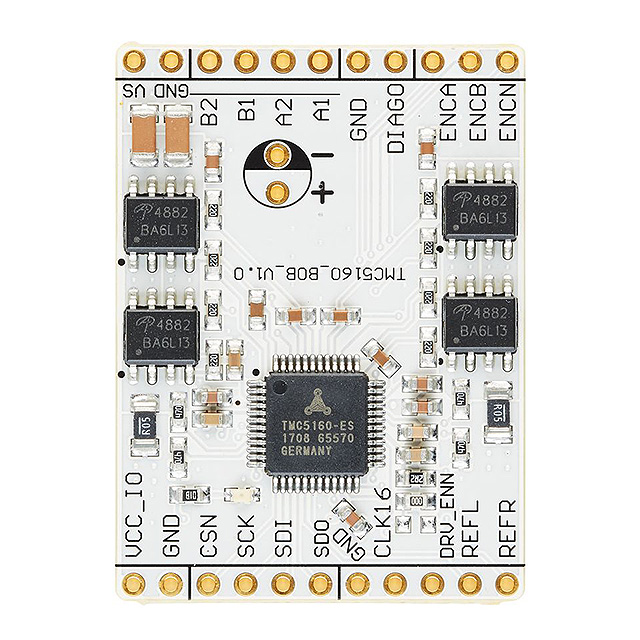
The TMC5160-BOB is a breakout board specifically designed to facilitate the use of the TMC5160 stepper motor driver IC, manufactured by Trinamic, now part of Maxim Integrated. This board simplifies the process of controlling stepper motors for applications such as 3D printers, CNC machines, and robotics. The TMC5160-BOB provides an accessible interface to the sophisticated features of the TMC5160 driver, including high-resolution microstepping, sensorless load detection, and stealthChop2 for silent operation.

Explore Projects Built with TMC5160-BOB

Use Cirkit Designer to design, explore, and prototype these projects online. Some projects support real-time simulation. Click "Open Project" to start designing instantly!
Arduino Mega 2560 Based Security System with Fingerprint Authentication and SMS Alerts
Image of Door security system: A project utilizing TMC5160-BOB in a practical application
This circuit features an Arduino Mega 2560 microcontroller interfaced with a SIM800L GSM module, two fingerprint scanners, an I2C LCD display, an IR sensor, and a piezo buzzer. Power management is handled by a PowerBoost 1000 Basic Pad USB, a TP4056 charging module, and a Li-ion 18650 battery, with an option to use a Mini AC-DC 110V-230V to 5V 700mA module for direct power supply. The primary functionality appears to be a security system with GSM communication capabilities, biometric access control, and visual/audible feedback.
Cirkit Designer LogoOpen Project in Cirkit Designer
STM32F103C8T6 Bluetooth-Controlled Arcade Joystick Interface
Image of RC카 조이스틱: A project utilizing TMC5160-BOB in a practical application
This circuit features an STM32F103C8T6 microcontroller interfaced with a Bluetooth HC-06 module for wireless communication and an Adafruit Arcade Joystick for user input. The microcontroller's pins B0 and B10 are connected to the TXD and RXD pins of the Bluetooth module, enabling serial communication, while pins B14 and B15 interface with the joystick's directional controls. The circuit is powered by a battery, with power distribution managed through the microcontroller's 3.3V pin and common ground connections.
Cirkit Designer LogoOpen Project in Cirkit Designer
Battery-Powered Health Monitoring System with Nucleo WB55RG and OLED Display
Image of Pulsefex: A project utilizing TMC5160-BOB in a practical application
This circuit is a multi-sensor data acquisition system that uses a Nucleo WB55RG microcontroller to interface with a digital temperature sensor (TMP102), a pulse oximeter and heart-rate sensor (MAX30102), and a 0.96" OLED display via I2C. Additionally, it includes a Sim800l module for GSM communication, powered by a 3.7V LiPo battery.
Cirkit Designer LogoOpen Project in Cirkit Designer
Bluetooth Audio Receiver with Battery-Powered Amplifier and Loudspeakers
Image of speaker bluetooh portable: A project utilizing TMC5160-BOB in a practical application
This circuit is a Bluetooth-enabled audio system powered by a rechargeable 18650 Li-ion battery. It includes a TP4056 module for battery charging and protection, a PAM8403 amplifier with volume control to drive two loudspeakers, and a Bluetooth audio receiver to wirelessly receive audio signals.
Cirkit Designer LogoOpen Project in Cirkit Designer

Explore Projects Built with TMC5160-BOB

Use Cirkit Designer to design, explore, and prototype these projects online. Some projects support real-time simulation. Click "Open Project" to start designing instantly!
Image of Door security system: A project utilizing TMC5160-BOB in a practical application
Arduino Mega 2560 Based Security System with Fingerprint Authentication and SMS Alerts
This circuit features an Arduino Mega 2560 microcontroller interfaced with a SIM800L GSM module, two fingerprint scanners, an I2C LCD display, an IR sensor, and a piezo buzzer. Power management is handled by a PowerBoost 1000 Basic Pad USB, a TP4056 charging module, and a Li-ion 18650 battery, with an option to use a Mini AC-DC 110V-230V to 5V 700mA module for direct power supply. The primary functionality appears to be a security system with GSM communication capabilities, biometric access control, and visual/audible feedback.
Cirkit Designer LogoOpen Project in Cirkit Designer
Image of RC카 조이스틱: A project utilizing TMC5160-BOB in a practical application
STM32F103C8T6 Bluetooth-Controlled Arcade Joystick Interface
This circuit features an STM32F103C8T6 microcontroller interfaced with a Bluetooth HC-06 module for wireless communication and an Adafruit Arcade Joystick for user input. The microcontroller's pins B0 and B10 are connected to the TXD and RXD pins of the Bluetooth module, enabling serial communication, while pins B14 and B15 interface with the joystick's directional controls. The circuit is powered by a battery, with power distribution managed through the microcontroller's 3.3V pin and common ground connections.
Cirkit Designer LogoOpen Project in Cirkit Designer
Image of Pulsefex: A project utilizing TMC5160-BOB in a practical application
Battery-Powered Health Monitoring System with Nucleo WB55RG and OLED Display
This circuit is a multi-sensor data acquisition system that uses a Nucleo WB55RG microcontroller to interface with a digital temperature sensor (TMP102), a pulse oximeter and heart-rate sensor (MAX30102), and a 0.96" OLED display via I2C. Additionally, it includes a Sim800l module for GSM communication, powered by a 3.7V LiPo battery.
Cirkit Designer LogoOpen Project in Cirkit Designer
Image of speaker bluetooh portable: A project utilizing TMC5160-BOB in a practical application
Bluetooth Audio Receiver with Battery-Powered Amplifier and Loudspeakers
This circuit is a Bluetooth-enabled audio system powered by a rechargeable 18650 Li-ion battery. It includes a TP4056 module for battery charging and protection, a PAM8403 amplifier with volume control to drive two loudspeakers, and a Bluetooth audio receiver to wirelessly receive audio signals.
Cirkit Designer LogoOpen Project in Cirkit Designer

Common Applications and Use Cases

  • 3D Printers
  • CNC Machines
  • Robotics
  • Precision Positioning Systems
  • Automated Equipment

Technical Specifications

Key Technical Details

  • Motor Supply Voltage (VM): 8 - 35 V
  • Logic Supply Voltage (VIO): 3.3 - 5 V
  • Phase Current: Up to 2.8A RMS, 4A Peak
  • Microstepping: Up to 1/256
  • Interface: SPI

Pin Configuration and Descriptions

Pin Number Pin Name Description
1 GND Ground connection
2 VM Motor supply voltage (8-35V)
3 VIO Logic supply voltage (3.3-5V)
4 EN Enable motor output (active low)
5 MS1 Microstep selection 1
6 MS2 Microstep selection 2
7 DIAG0 Diagnostic output
8 STEP Step input
9 DIR Direction input
10 GND Ground connection
... ... ...

Note: This is a partial list. Refer to the TMC5160 datasheet for the full pinout and descriptions.

Usage Instructions

How to Use the Component in a Circuit

  1. Power Supply: Connect a suitable power supply to the VM and GND pins for the motor and VIO for the logic level.
  2. Motor Connection: Attach the stepper motor wires to the respective phase outputs on the breakout board.
  3. Control Signals: Connect the STEP and DIR pins to the controlling microcontroller or processor to input stepping signals and direction control.
  4. Microstepping Configuration: Set the microstepping resolution by configuring the MS1 and MS2 pins according to the desired setting.
  5. Enable Motor: The EN pin can be used to enable or disable the motor output. Pull this pin low to enable the motor.

Important Considerations and Best Practices

  • Ensure that the power supply voltage does not exceed the specified limits for VM and VIO.
  • Use proper decoupling capacitors close to the board to minimize voltage spikes.
  • Configure the current limit according to the motor specifications to prevent damage.
  • Implement proper cooling if operating the driver at high currents for extended periods.
  • Always disconnect power before making or changing connections to the board.

Troubleshooting and FAQs

Common Issues Users Might Face

  • Motor not moving: Check power supply, connections, and ensure that the EN pin is pulled low.
  • Overheating: Verify current settings and improve cooling if necessary.
  • Noise during operation: Adjust stealthChop2 settings or check for mechanical obstructions.

Solutions and Tips for Troubleshooting

  • Double-check wiring and solder joints for any loose connections or shorts.
  • Use a multimeter to verify power supply voltages and continuity of connections.
  • Consult the TMC5160 datasheet for detailed configuration and troubleshooting information.

FAQs

Q: Can I use the TMC5160-BOB with an Arduino UNO? A: Yes, the TMC5160-BOB can be controlled with an Arduino UNO using digital I/O pins for STEP, DIR, and EN signals, and SPI for configuration.

Q: What is the maximum current the TMC5160-BOB can handle? A: The TMC5160-BOB can handle up to 2.8A RMS per phase without additional cooling.

Q: How do I set the current limit on the TMC5160-BOB? A: The current limit is set via SPI commands. Refer to the TMC5160 datasheet for the specific register settings.

Example Code for Arduino UNO

#include <SPI.h>

// Define pin connections & motor interface
#define EN_PIN    8  // Enable
#define DIR_PIN   7  // Direction
#define STEP_PIN  6  // Step
#define CS_PIN    5  // Chip select for SPI
#define MOSI_PIN  11 // Master Out Slave In for SPI
#define MISO_PIN  12 // Master In Slave Out for SPI
#define SCK_PIN   13 // Serial Clock for SPI

void setup() {
  pinMode(EN_PIN, OUTPUT);
  pinMode(DIR_PIN, OUTPUT);
  pinMode(STEP_PIN, OUTPUT);
  pinMode(CS_PIN, OUTPUT);

  // Set the initial states
  digitalWrite(EN_PIN, LOW); // Enable driver in active low
  digitalWrite(DIR_PIN, HIGH); // Set direction
  digitalWrite(CS_PIN, HIGH); // Deselect chip

  // Initialize SPI
  SPI.begin();
  SPI.beginTransaction(SPISettings(1000000, MSBFIRST, SPI_MODE3));
  
  // Send configuration to TMC5160 via SPI
  // Example: Write to CHOPCONF register (0x6B)
  digitalWrite(CS_PIN, LOW);
  SPI.transfer(0x6B); // Address byte
  SPI.transfer(0x00); // Data byte 1
  SPI.transfer(0x00); // Data byte 2
  SPI.transfer(0x00); // Data byte 3
  SPI.transfer(0x00); // Data byte 4
  digitalWrite(CS_PIN, HIGH);
}

void loop() {
  // Create a simple stepping pattern
  digitalWrite(STEP_PIN, HIGH);
  delay(1); // Wait 1ms
  digitalWrite(STEP_PIN, LOW);
  delay(1); // Wait 1ms
}

Note: The above code is a basic example to get started. For full functionality, additional configuration via SPI is required. Refer to the TMC5160 datasheet for detailed register settings and advanced features.


This documentation is provided for informational purposes only and is subject to change without notice. The TMC5160-BOB breakout board is a product of Trinamic, and all trademarks are the property of their respective owners.