How to Use PowerBoard step down: Examples, Pinouts, and Specs
Introduction
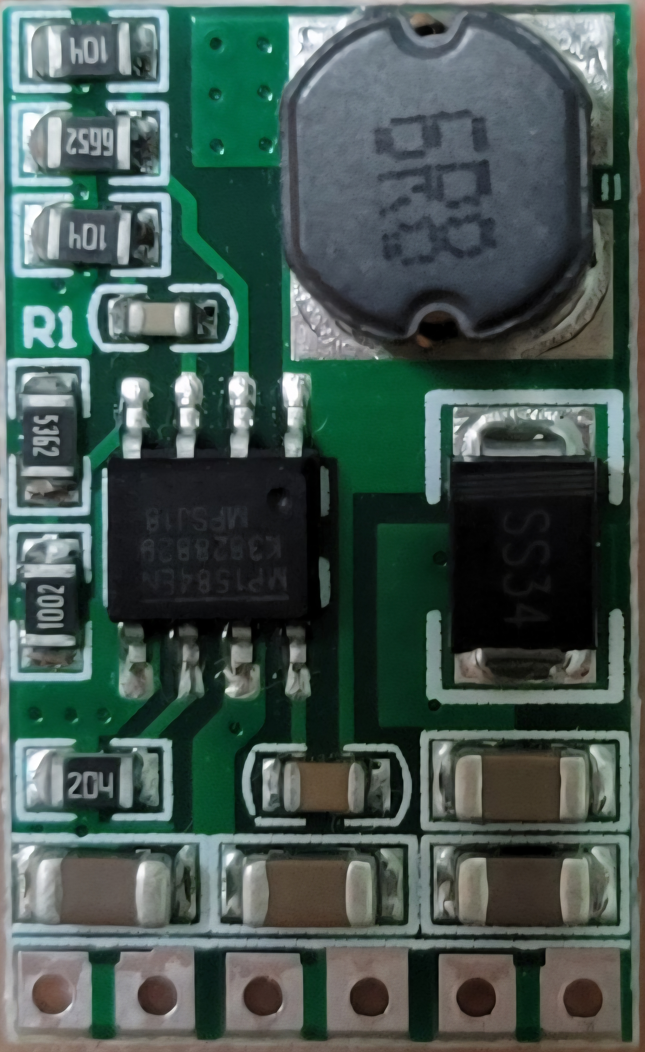
The PowerBoard Step Down is a voltage regulator module designed to reduce a higher input voltage to a lower, stable output voltage. This component is essential for powering low-voltage devices from higher-voltage power sources, ensuring safe and efficient operation. It is widely used in applications such as battery-powered systems, embedded electronics, robotics, and DIY projects.
Common applications and use cases:
- Powering microcontrollers (e.g., Arduino, Raspberry Pi) from higher voltage sources.
- Regulating voltage for sensors, motors, and other low-voltage components.
- Battery management systems and portable electronics.
- DIY projects requiring stable voltage conversion.
Explore Projects Built with PowerBoard step down


Explore Projects Built with PowerBoard step down
Technical Specifications
The PowerBoard Step Down module is designed to handle a variety of input and output voltage ranges, making it versatile for different applications. Below are the key technical details:
General Specifications
- Input Voltage Range: 4.5V to 40V DC
- Output Voltage Range: 1.25V to 37V DC (adjustable)
- Maximum Output Current: 3A (with proper heat dissipation)
- Efficiency: Up to 92% (depending on input/output voltage difference)
- Switching Frequency: 150 kHz
- Operating Temperature: -40°C to +85°C
- Dimensions: 43mm x 21mm x 14mm
Pin Configuration and Descriptions
The PowerBoard Step Down module typically has the following pin layout:
| Pin Name | Description |
|---|---|
| VIN | Input voltage pin. Connect to the higher voltage source (e.g., battery, adapter). |
| GND | Ground pin. Connect to the ground of the power source and the load. |
| VOUT | Output voltage pin. Provides the regulated lower voltage to the load. |
| ADJ | Adjustment pin. Used to set the output voltage using a potentiometer or resistor. |
Usage Instructions
How to Use the PowerBoard Step Down in a Circuit
Connect the Input Voltage:
- Attach the positive terminal of your power source to the
VINpin. - Connect the ground terminal of your power source to the
GNDpin.
- Attach the positive terminal of your power source to the
Set the Output Voltage:
- Use the onboard potentiometer to adjust the output voltage.
- Turn the potentiometer clockwise to increase the output voltage and counterclockwise to decrease it.
- Use a multimeter to measure the output voltage at the
VOUTpin to ensure it matches your desired value.
Connect the Load:
- Attach the positive terminal of your load to the
VOUTpin. - Connect the ground terminal of your load to the
GNDpin.
- Attach the positive terminal of your load to the
Power On:
- Once all connections are secure, power on the input source. The module will regulate the voltage and provide a stable output.
Important Considerations and Best Practices
- Heat Dissipation: If the module is operating near its maximum current rating (3A), ensure proper heat dissipation by attaching a heatsink or providing adequate airflow.
- Input Voltage: Always ensure the input voltage is within the specified range (4.5V to 40V DC).
- Output Voltage Adjustment: Double-check the output voltage with a multimeter before connecting sensitive devices.
- Polarity: Ensure correct polarity when connecting the input and output terminals to avoid damage to the module.
Example: Using the PowerBoard Step Down with an Arduino UNO
The PowerBoard Step Down can be used to power an Arduino UNO from a 12V battery. Below is an example setup:
- Connect the 12V battery's positive terminal to the
VINpin and the negative terminal to theGNDpin. - Adjust the output voltage to 5V using the potentiometer.
- Connect the
VOUTpin to the Arduino's 5V pin and theGNDpin to the Arduino's GND pin.
Here is a simple Arduino code example to blink an LED, powered by the regulated 5V output:
// Simple LED Blink Example
// Ensure the PowerBoard Step Down is set to 5V before connecting to the Arduino.

const int ledPin = 13; // Pin connected to the onboard LED

void setup() {
  pinMode(ledPin, OUTPUT); // Set the LED pin as an output
}

void loop() {
  digitalWrite(ledPin, HIGH); // Turn the LED on
  delay(1000);                // Wait for 1 second
  digitalWrite(ledPin, LOW);  // Turn the LED off
  delay(1000);                // Wait for 1 second
}
Troubleshooting and FAQs
Common Issues and Solutions
No Output Voltage:
- Check the input voltage to ensure it is within the specified range.
- Verify all connections, especially the polarity of the input and output terminals.
- Ensure the potentiometer is not set to the minimum output voltage.
Overheating:
- If the module becomes excessively hot, reduce the load current or improve heat dissipation with a heatsink or fan.
- Ensure the input voltage is not too high relative to the output voltage.
Fluctuating Output Voltage:
- Check for loose connections or poor solder joints.
- Ensure the input voltage is stable and not dropping under load.
Output Voltage Not Adjustable:
- Verify that the potentiometer is functioning correctly. If damaged, replace it.
- Ensure the input voltage is at least 1.5V higher than the desired output voltage.
FAQs
Q: Can I use the PowerBoard Step Down to charge a battery?
A: Yes, but ensure the output voltage is set to the appropriate charging voltage for the battery type. Additionally, use a current-limiting circuit if required.
Q: What happens if I exceed the maximum input voltage?
A: Exceeding the input voltage range (40V) can permanently damage the module. Always use a power source within the specified range.
Q: Can I use this module for AC voltage?
A: No, the PowerBoard Step Down is designed for DC input only. Using AC voltage will damage the module.
Q: Is the module safe for sensitive electronics?
A: Yes, as long as the output voltage is properly adjusted and stable, it is safe for sensitive devices like microcontrollers and sensors.