
How to Use Pogo Pin Probe Clip - 2x5 1.27mm Pitch SWD: Examples, Pinouts, and Specs
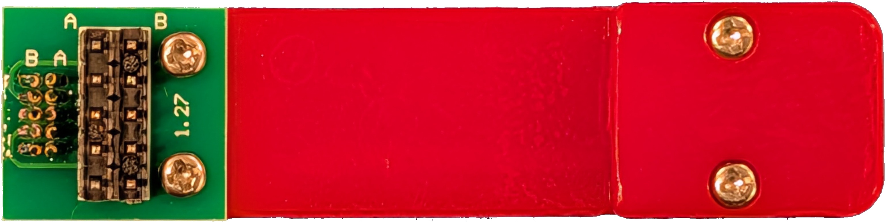
 Design with Pogo Pin Probe Clip - 2x5 1.27mm Pitch SWD in Cirkit Designer
Introduction
The Pogo Pin Probe Clip - 2x5 1.27mm Pitch SWD (Manufacturer: Adafruit, Part ID: 5434) is a specialized connector designed for making temporary, reliable connections to test points on a circuit board. It features a grid of pogo pins arranged in a 2x5 configuration with a 1.27mm pitch, making it ideal for debugging and programming tasks, particularly in Serial Wire Debug (SWD) applications.
This component is widely used in embedded systems development, where it facilitates quick and non-permanent connections to microcontroller programming headers. Its spring-loaded pogo pins ensure consistent electrical contact without the need for soldering, making it a valuable tool for prototyping, testing, and debugging.
Explore Projects Built with Pogo Pin Probe Clip - 2x5 1.27mm Pitch SWD
 Open Project in Cirkit Designer
 Open Project in Cirkit Designer
 Open Project in Cirkit Designer
 Open Project in Cirkit Designer
Explore Projects Built with Pogo Pin Probe Clip - 2x5 1.27mm Pitch SWD
Open Project in Cirkit DesignerOpen Project in Cirkit DesignerOpen Project in Cirkit DesignerOpen Project in Cirkit DesignerCommon Applications
- SWD Programming and Debugging: Used to interface with ARM Cortex microcontrollers for programming and debugging.
- Prototyping: Temporary connections to PCBs during development.
- Testing: Connecting to test points for signal analysis or diagnostics.
- Firmware Updates: Programming devices without requiring permanent connectors.
Technical Specifications
Key Technical Details
| Parameter | Value |
|---|---|
| Manufacturer | Adafruit |
| Part ID | 5434 |
| Pin Configuration | 2x5 grid (10 pins total) |
| Pin Pitch | 1.27mm |
| Connector Type | Pogo pin (spring-loaded) |
| Maximum Current per Pin | 1A |
| Contact Resistance | < 50 mΩ |
| Operating Temperature | -40°C to +85°C |
| Dimensions | 20mm x 10mm x 5mm (approx.) |
| Cable Length | 150mm |
Pin Configuration and Descriptions
The pogo pin probe clip is designed to interface with a standard 2x5 SWD header. Below is the pinout for the 2x5 configuration:
| Pin Number | Signal Name | Description |
|---|---|---|
| 1 | VCC | Target board power supply (3.3V/5V) |
| 2 | SWDIO | Serial Wire Debug I/O |
| 3 | GND | Ground |
| 4 | SWCLK | Serial Wire Debug Clock |
| 5 | GND | Ground |
| 6 | NC | Not Connected |
| 7 | NC | Not Connected |
| 8 | NC | Not Connected |
| 9 | GND | Ground |
| 10 | RESET | Target board reset |
Usage Instructions
How to Use the Component in a Circuit
- Align the Clip with the Target Header: Ensure the pogo pin probe clip is aligned with the 2x5 SWD header on the target PCB. The clip should match the pinout configuration described above.
- Secure the Connection: Gently press the clip onto the header to establish a reliable connection. The spring-loaded pogo pins will ensure consistent contact.
- Connect to Debugger/Programmer: Attach the other end of the cable to your SWD-compatible debugger or programmer (e.g., ST-Link, J-Link, or an Arduino-based SWD programmer).
- Power the Target Board: Ensure the target board is powered appropriately (3.3V or 5V, depending on the microcontroller).
- Begin Debugging/Programming: Use your preferred software tools (e.g., OpenOCD, Keil, or PlatformIO) to program or debug the target microcontroller.
Important Considerations and Best Practices
- Pin Alignment: Double-check the alignment of the clip with the target header to avoid incorrect connections.
- Avoid Excessive Force: Do not apply excessive pressure when attaching the clip, as this may damage the pogo pins or the PCB.
- Stable Connection: Ensure the clip remains stable during use to prevent intermittent connections.
- Voltage Compatibility: Verify that the target board's voltage levels are compatible with the debugger/programmer.
- Cable Management: Keep the cable untangled and secure to avoid accidental disconnections.
Example: Using with an Arduino UNO as an SWD Programmer
The pogo pin probe clip can be used with an Arduino UNO configured as an SWD programmer. Below is an example Arduino sketch for programming an ARM Cortex microcontroller:
// Example: Arduino UNO as SWD Programmer
// This sketch configures the Arduino UNO to act as an SWD programmer
// for ARM Cortex microcontrollers. Ensure proper pin connections.

// Include necessary libraries
#include <SWDProgrammer.h>  // Hypothetical library for SWD programming

// Define SWD pins on Arduino UNO
#define SWDIO_PIN 8  // Connect to SWDIO on target
#define SWCLK_PIN 9  // Connect to SWCLK on target
#define RESET_PIN 10 // Connect to RESET on target

void setup() {
  // Initialize SWD interface
  SWD.begin(SWDIO_PIN, SWCLK_PIN, RESET_PIN);

  // Optional: Reset the target microcontroller
  SWD.resetTarget();

  // Example: Write firmware to target
  if (SWD.writeFirmware("firmware.bin")) {
    Serial.println("Firmware upload successful!");
  } else {
    Serial.println("Firmware upload failed.");
  }
}

void loop() {
  // No continuous operation required
}
Troubleshooting and FAQs
Common Issues and Solutions
Intermittent Connections
- Cause: Misalignment of the pogo pin clip with the target header.
- Solution: Realign the clip and ensure it is securely pressed onto the header.
No Communication with Target
- Cause: Incorrect pin connections or voltage mismatch.
- Solution: Verify the pinout and ensure the target board is powered correctly.
Damaged Pogo Pins
- Cause: Excessive force or wear over time.
- Solution: Replace the pogo pin probe clip if the pins are bent or no longer spring-loaded.
Debugger Not Recognized
- Cause: Faulty cable or incorrect software configuration.
- Solution: Check the cable connections and ensure the debugger is properly configured in the software.
FAQs
Q: Can this clip be used with a 1.27mm pitch JTAG header?
A: Yes, as long as the pinout matches the 2x5 configuration, the clip can be used with JTAG headers.
Q: Is the clip compatible with 1.8V target boards?
A: The clip itself is passive, but ensure your debugger/programmer supports 1.8V logic levels.
Q: How durable are the pogo pins?
A: The pogo pins are designed for repeated use, but their lifespan depends on proper handling and alignment.
Q: Can I use this clip for permanent connections?
A: No, the pogo pin probe clip is intended for temporary connections only. For permanent connections, consider soldering a header.
This documentation provides a comprehensive guide to using the Pogo Pin Probe Clip - 2x5 1.27mm Pitch SWD effectively. For further assistance, refer to Adafruit's official resources or contact their support team.