How to Use Crystal: Examples, Pinouts, and Specs
Introduction
A crystal oscillator, commonly referred to as a crystal, is a passive electronic component that utilizes the piezoelectric effect to generate a stable frequency when a voltage is applied. These components are crucial in timing circuits, serving as the heartbeat for devices that require precise clock signals, such as microcontrollers, watches, and communication systems.
Explore Projects Built with Crystal

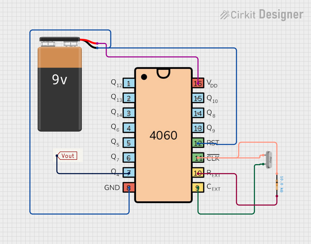
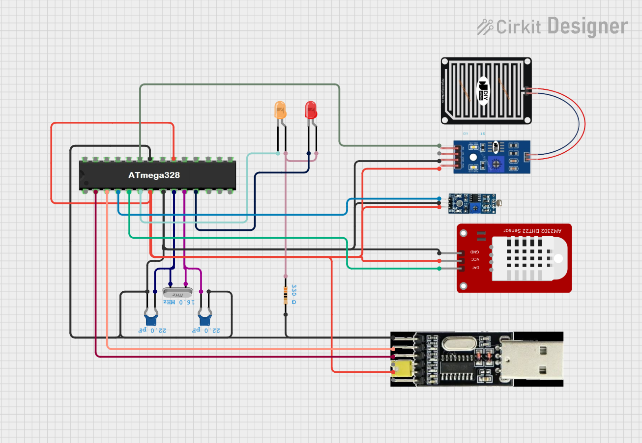

Explore Projects Built with Crystal
Common Applications and Use Cases
- Clock generation for microcontrollers and CPUs
- Frequency reference for communication systems
- Timekeeping in watches and clocks
- Stabilizing frequencies in RF transmitters and receivers
Technical Specifications
Key Technical Details
- Frequency Range: Typically from 32.768 kHz to hundreds of MHz
- Frequency Tolerance: ±10 ppm to ±100 ppm or more, depending on quality
- Load Capacitance: Specified in pF, typically 8 to 32 pF
- Drive Level: The power level at which the crystal is specified to operate, usually in µW
- Equivalent Series Resistance (ESR): The internal resistance, lower values are better for stability
- Operating Temperature Range: The range over which the crystal will operate within its specified parameters
Pin Configuration and Descriptions
| Pin Number | Description |
|---|---|
| 1 | Crystal Input |
| 2 | Crystal Ground (GND) |
Usage Instructions
How to Use the Component in a Circuit
- Selecting the Crystal: Choose a crystal with the appropriate frequency and load capacitance for your application.
- Circuit Integration: Connect the crystal in parallel with two load capacitors to ground. The value of these capacitors depends on the crystal's load capacitance specification and the input and output capacitance of the driving circuit.
- Connection to Microcontroller: Connect the crystal across the oscillator pins of the microcontroller, ensuring correct polarity if specified.
Important Considerations and Best Practices
- Load Capacitance Matching: Ensure that the total load capacitance seen by the crystal matches its specified load capacitance.
- Drive Level Compliance: Do not exceed the recommended drive level to avoid damaging the crystal or causing premature aging.
- Temperature Stability: Be aware of the operating temperature range and choose a crystal with appropriate temperature compensation if necessary.
- Physical Mounting: Minimize mechanical stress and vibration, as these can affect the frequency stability.
Troubleshooting and FAQs
Common Issues Users Might Face
- Inaccurate Clock Frequency: This can be due to incorrect load capacitance or temperature variations outside the specified range.
- No Oscillation: This may occur if the drive level is too low or if there is a poor connection to the oscillator circuit.
Solutions and Tips for Troubleshooting
- Check Load Capacitance: Verify that the load capacitors are the correct value and are properly connected.
- Inspect Connections: Ensure that the crystal is properly soldered and that there are no cold solder joints.
- Drive Level Adjustment: If the crystal does not oscillate, increase the drive level cautiously within the specified limits.
FAQs
Q: Can I use any crystal with my microcontroller? A: No, you must use a crystal that matches the specifications required by the microcontroller, particularly the frequency and load capacitance.
Q: How do I calculate the load capacitors for my crystal? A: The load capacitance (C_L) can be calculated using the formula: C_L = (2 * C_load) - (C_stray + C_pin), where C_load is the crystal's specified load capacitance, and C_stray and C_pin are the stray capacitance and pin capacitance of the circuit, respectively.
Q: What happens if I use a crystal with a higher frequency than specified? A: Using a crystal with a higher frequency than specified can lead to system instability, incorrect timing, and potential failure to oscillate.
Example Code for Arduino UNO
// Example code to set up an external crystal oscillator with an Arduino UNO

void setup() {
  // Assuming the crystal is connected to the appropriate pins (9 and 10 on UNO)
  // No additional setup code is required as the Arduino automatically uses the external crystal if connected.
}

void loop() {
  // Your application code goes here
}

// Note: The Arduino UNO typically uses a 16 MHz crystal. If you are using a crystal with a different frequency,
// you may need to adjust the fuse settings or use a different board definition that matches your crystal's frequency.
Remember that the Arduino UNO has a built-in 16 MHz crystal, and the above code is for illustrative purposes. If you are using a different microcontroller or a custom setup, you may need to configure the hardware registers to use the external crystal oscillator.