Cirkit Designer Logo
Cirkit Designer
Your all-in-one circuit design IDE
Home / 
Component Documentation

How to Use Adafruit 8x16 LED Matrix FeatherWing - Red: Examples, Pinouts, and Specs

Image of Adafruit 8x16 LED Matrix FeatherWing - Red
Cirkit Designer LogoDesign with Adafruit 8x16 LED Matrix FeatherWing - Red in Cirkit Designer

Introduction

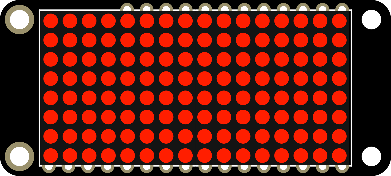
The Adafruit 8x16 LED Matrix FeatherWing in Red is a versatile and visually appealing electronic component that offers a grid of 128 red LEDs arranged in an 8x16 matrix. This LED matrix is designed to be used with the Adafruit Feather series of development boards, providing a compact and easy-to-use display option for a variety of projects. Common applications include scrolling text displays, animations, simple graphics, and interactive games.

Explore Projects Built with Adafruit 8x16 LED Matrix FeatherWing - Red

Use Cirkit Designer to design, explore, and prototype these projects online. Some projects support real-time simulation. Click "Open Project" to start designing instantly!
Arduino-Controlled RGB LED Matrix Display
Image of SMD2121 Led screen: A project utilizing Adafruit 8x16 LED Matrix FeatherWing - Red in a practical application
This circuit connects an Arduino UNO R4 WiFi microcontroller to a 64x32 LED matrix display. The Arduino is configured to control the LED matrix, sending color data and control signals to display various colors across the matrix. The embedded code on the Arduino cycles through a range of colors, filling the entire LED matrix with each color in sequence.
Cirkit Designer LogoOpen Project in Cirkit Designer
Arduino UNO Controlled LED Matrix Display with Interactive Pushbuttons
Image of Cykel: A project utilizing Adafruit 8x16 LED Matrix FeatherWing - Red in a practical application
This circuit features an Arduino UNO microcontroller connected to multiple 8x8 LED matrix displays and pushbuttons. The pushbuttons are interfaced with digital pins D2, D3, and D4 on the Arduino for input, while the LED matrices are connected to digital pins D5 through D10 for control signals. Additionally, there is a single red LED with a series resistor connected to pin D12, likely used as an indicator light.
Cirkit Designer LogoOpen Project in Cirkit Designer
Arduino UNO WiFi-Controlled LED Matrix Display
Image of SMD2121 Led screen - r4: A project utilizing Adafruit 8x16 LED Matrix FeatherWing - Red in a practical application
This circuit consists of an Arduino UNO R4 WiFi microcontroller connected to a 64x32 LED matrix. The Arduino controls the LED matrix by sending signals to various pins to display different colors and patterns, as defined in the embedded code.
Cirkit Designer LogoOpen Project in Cirkit Designer
Arduino-Controlled Dual WS2812 RGB LED Matrix Eye Animation Display
Image of eye project: A project utilizing Adafruit 8x16 LED Matrix FeatherWing - Red in a practical application
This circuit consists of an Arduino UNO microcontroller connected to two daisy-chained WS2812 RGB LED 8x8 matrices. The Arduino controls the LED matrices to display patterns that simulate a slow blinking human eyes effect. The code for the Arduino is written to create and cycle through different eye patterns, varying from open to half-closed to closed, to achieve the blinking effect.
Cirkit Designer LogoOpen Project in Cirkit Designer

Explore Projects Built with Adafruit 8x16 LED Matrix FeatherWing - Red

Use Cirkit Designer to design, explore, and prototype these projects online. Some projects support real-time simulation. Click "Open Project" to start designing instantly!
Image of SMD2121 Led screen: A project utilizing Adafruit 8x16 LED Matrix FeatherWing - Red in a practical application
Arduino-Controlled RGB LED Matrix Display
This circuit connects an Arduino UNO R4 WiFi microcontroller to a 64x32 LED matrix display. The Arduino is configured to control the LED matrix, sending color data and control signals to display various colors across the matrix. The embedded code on the Arduino cycles through a range of colors, filling the entire LED matrix with each color in sequence.
Cirkit Designer LogoOpen Project in Cirkit Designer
Image of Cykel: A project utilizing Adafruit 8x16 LED Matrix FeatherWing - Red in a practical application
Arduino UNO Controlled LED Matrix Display with Interactive Pushbuttons
This circuit features an Arduino UNO microcontroller connected to multiple 8x8 LED matrix displays and pushbuttons. The pushbuttons are interfaced with digital pins D2, D3, and D4 on the Arduino for input, while the LED matrices are connected to digital pins D5 through D10 for control signals. Additionally, there is a single red LED with a series resistor connected to pin D12, likely used as an indicator light.
Cirkit Designer LogoOpen Project in Cirkit Designer
Image of SMD2121 Led screen - r4: A project utilizing Adafruit 8x16 LED Matrix FeatherWing - Red in a practical application
Arduino UNO WiFi-Controlled LED Matrix Display
This circuit consists of an Arduino UNO R4 WiFi microcontroller connected to a 64x32 LED matrix. The Arduino controls the LED matrix by sending signals to various pins to display different colors and patterns, as defined in the embedded code.
Cirkit Designer LogoOpen Project in Cirkit Designer
Image of eye project: A project utilizing Adafruit 8x16 LED Matrix FeatherWing - Red in a practical application
Arduino-Controlled Dual WS2812 RGB LED Matrix Eye Animation Display
This circuit consists of an Arduino UNO microcontroller connected to two daisy-chained WS2812 RGB LED 8x8 matrices. The Arduino controls the LED matrices to display patterns that simulate a slow blinking human eyes effect. The code for the Arduino is written to create and cycle through different eye patterns, varying from open to half-closed to closed, to achieve the blinking effect.
Cirkit Designer LogoOpen Project in Cirkit Designer

Technical Specifications

Key Technical Details

  • Dimensions: 16mm x 32mm x 1.6mm / 0.63" x 1.26" x 0.06"
  • Weight: 4.7 grams
  • LED Color: Red
  • Matrix Size: 8x16 (128 LEDs total)
  • Operating Voltage: 3.3V to 5V DC
  • Max Current Draw: 320mA at 5V (all LEDs on)
  • Interface: I2C
  • I2C Addresses: 0x70 (default), selectable with jumpers

Pin Configuration and Descriptions

Pin Name Description
GND Ground connection
VCC Power supply (3.3V to 5V DC)
SDA I2C Data line
SCL I2C Clock line
ADDR I2C Address selection (with solder jumpers)
RST Reset pin (optional use)

Usage Instructions

Connecting to an Arduino UNO

  1. Power Connections:

    • Connect the VCC pin to the 5V output on the Arduino UNO.
    • Connect the GND pin to one of the GND pins on the Arduino UNO.
  2. Data Connections:

    • Connect the SDA pin to the A4 pin (SDA) on the Arduino UNO.
    • Connect the SCL pin to the A5 pin (SCL) on the Arduino UNO.
  3. Library Installation:

    • Install the Adafruit_LED_Backpack library through the Arduino Library Manager.
  4. Programming:

    • Include the library in your sketch and initialize the display.

Example Arduino Code

#include <Wire.h>
#include <Adafruit_GFX.h>
#include <Adafruit_LEDBackpack.h>

Adafruit_8x16matrix matrix = Adafruit_8x16matrix();

void setup() {
  matrix.begin(0x70); // Start the LED matrix with the I2C address
  matrix.setBrightness(10); // Set brightness to a value between 0 and 15
}

void loop() {
  matrix.clear(); // Clear the matrix display
  matrix.setCursor(0, 0); // Set cursor at top-left corner
  matrix.print(F("Hello")); // Print a message to the matrix
  matrix.writeDisplay(); // Update the display with the new data
  delay(500); // Wait for half a second
}

Important Considerations and Best Practices

  • Power Requirements: Ensure that your power supply can handle the maximum current draw if all LEDs are lit.
  • Brightness Control: Adjust the brightness to suit your application and to manage power consumption.
  • I2C Addressing: If using multiple matrices, set unique I2C addresses using the ADDR solder jumpers.
  • Heat Dissipation: Be mindful of heat generation when operating at high brightness for extended periods.

Troubleshooting and FAQs

Common Issues

  • LEDs Not Lighting Up: Check connections and ensure the correct I2C address is used in your code.
  • Dim Display: Verify that the brightness is set correctly in your code and that the power supply is adequate.
  • Flickering Display: Ensure there is a stable power supply and check for loose connections.

Solutions and Tips

  • Power Supply: Use a dedicated power supply if the Arduino UNO cannot provide sufficient current.
  • Code Debugging: Use serial output to debug your code and confirm that the matrix is receiving commands.
  • I2C Scanning: Use an I2C scanner sketch to confirm the matrix's address if unsure.

FAQs

Q: Can I use this LED matrix with other microcontrollers? A: Yes, as long as the microcontroller supports I2C communication and can provide the necessary power.

Q: How do I change the I2C address? A: Solder or desolder the jumpers on the ADDR pin to set a new address.

Q: Can I daisy-chain multiple matrices? A: Yes, you can connect multiple matrices in series, but ensure each has a unique I2C address.

Q: Is it possible to use this matrix with a 3.3V system? A: Yes, the matrix can operate at 3.3V, but the LEDs may be dimmer compared to a 5V supply.

For further assistance, consult the Adafruit forums or the product's official documentation.