How to Use relay 3.3v: Examples, Pinouts, and Specs
Introduction
A relay is an electromechanical switch that allows a low-power control signal to operate a high-power circuit. The 3.3V relay is specifically designed to operate with a 3.3V control signal, making it ideal for use with microcontrollers and other low-voltage systems. It provides electrical isolation between the control circuit and the load, ensuring safety and protecting sensitive components.
Explore Projects Built with relay 3.3v

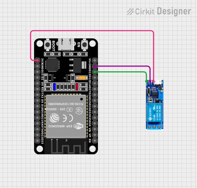
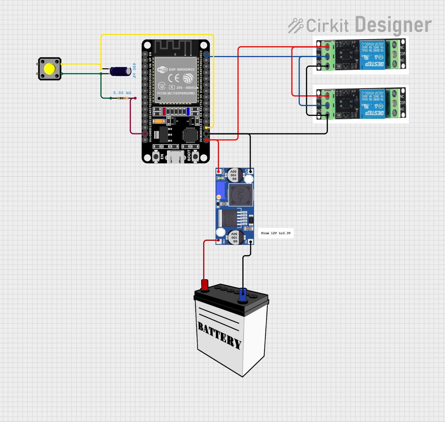
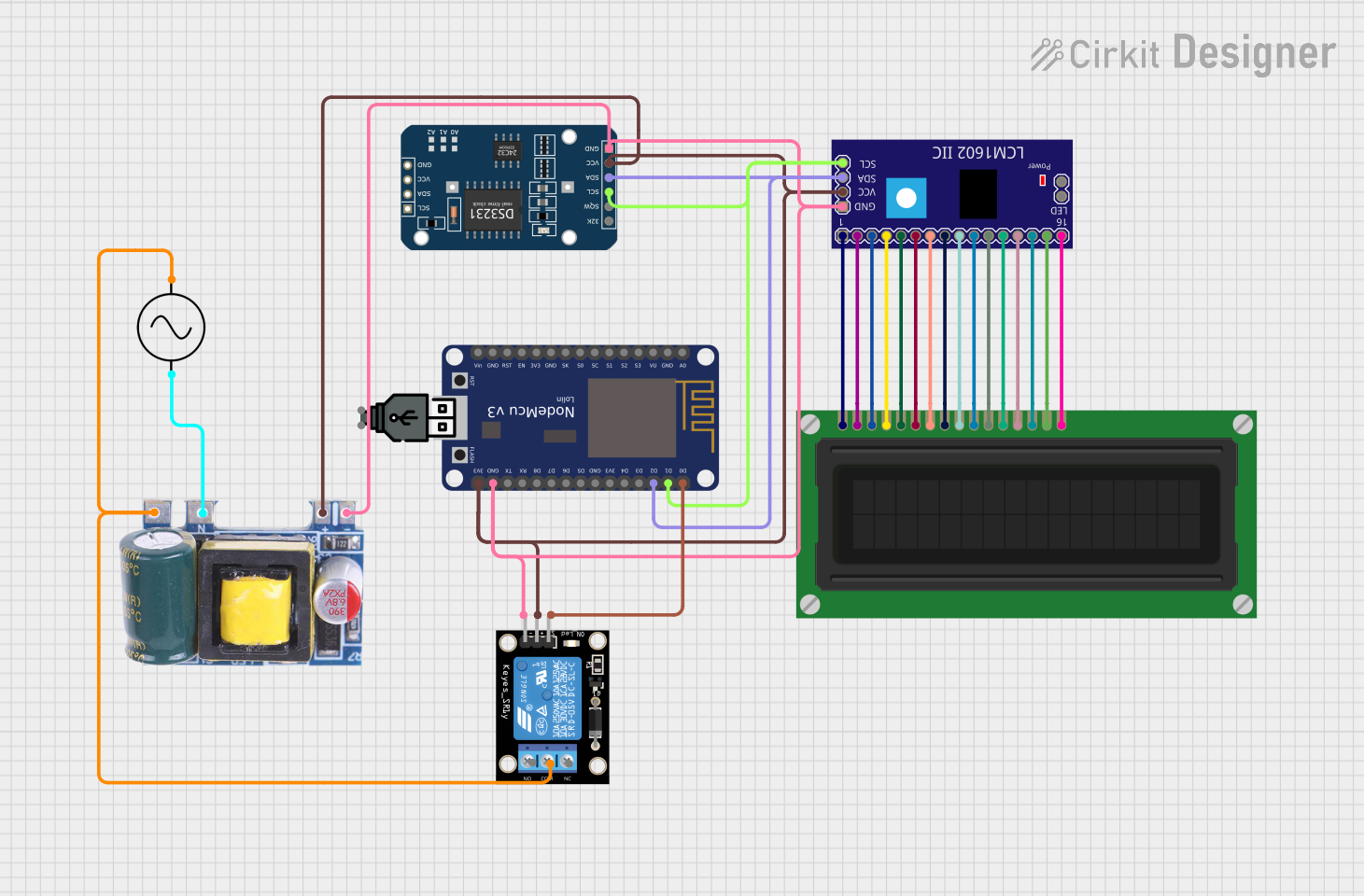
Explore Projects Built with relay 3.3v
Common Applications and Use Cases
- Home automation systems (e.g., controlling lights, fans, or appliances)
- Industrial control systems
- Motor control
- IoT devices and projects
- Switching high-power AC or DC loads using low-power microcontrollers like Arduino or Raspberry Pi
Technical Specifications
The following table outlines the key technical details of the 3.3V relay:
| Parameter | Value |
|---|---|
| Operating Voltage | 3.3V DC |
| Trigger Current | ~70mA |
| Contact Type | SPDT (Single Pole Double Throw) or SPST (Single Pole Single Throw) |
| Maximum Load Voltage | 250V AC / 30V DC |
| Maximum Load Current | 10A |
| Coil Resistance | ~45Ω |
| Electrical Isolation | Yes (via electromagnetic coil) |
| Switching Time | ~10ms (operate) / ~5ms (release) |
| Dimensions | Varies by model (e.g., 28mm x 12mm x 10mm) |
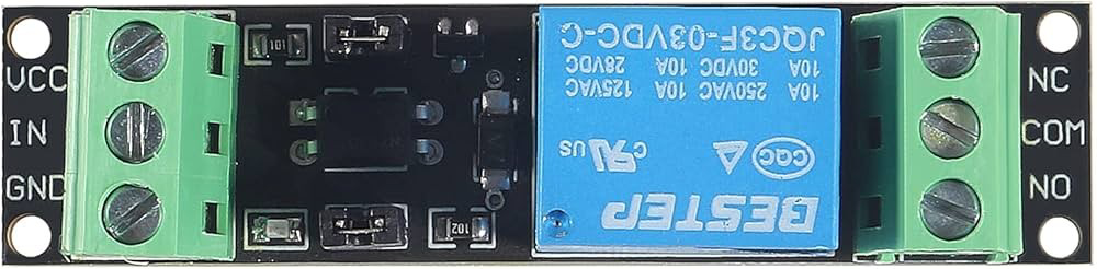
Pin Configuration and Descriptions
The 3.3V relay typically has 5 pins. The table below describes each pin:
| Pin Name | Description |
|---|---|
| VCC | Connect to the 3.3V power supply to energize the relay coil. |
| GND | Connect to the ground of the power supply. |
| IN (Signal) | Control signal input. A HIGH signal (3.3V) activates the relay. |
| COM (Common) | Common terminal for the load circuit. |
| NO (Normally Open) | Load terminal that remains disconnected until the relay is activated. |
| NC (Normally Closed) | Load terminal that remains connected until the relay is activated. |
Note: Some relay modules may include an onboard transistor and diode for easier interfacing with microcontrollers.
Usage Instructions
How to Use the Component in a Circuit
Power the Relay:
- Connect the VCC pin to a 3.3V power source and the GND pin to ground.
- Ensure the power supply can provide sufficient current (~70mA) to energize the relay coil.
Control the Relay:
- Connect the IN pin to a GPIO pin of your microcontroller (e.g., Arduino UNO).
- Set the GPIO pin HIGH (3.3V) to activate the relay and LOW (0V) to deactivate it.
Connect the Load:
- Identify whether you want to use the NO (Normally Open) or NC (Normally Closed) terminal.
- Connect one side of the load to the COM terminal and the other side to either the NO or NC terminal, depending on your application.
Add Protection:
- If the relay module does not include a flyback diode, add one across the relay coil to protect the circuit from voltage spikes.
- For inductive loads (e.g., motors), consider adding a snubber circuit to prevent arcing.
Example Circuit with Arduino UNO
Below is an example of how to connect and control a 3.3V relay with an Arduino UNO:
Circuit Connections:
- Relay VCC → Arduino 3.3V
- Relay GND → Arduino GND
- Relay IN → Arduino Digital Pin 7
- Relay COM → One terminal of the load
- Relay NO → Power source for the load
- Relay NC → Leave unconnected (if using NO)
Arduino Code:
// Define the relay control pin
const int relayPin = 7;

void setup() {
  // Set the relay pin as an output
  pinMode(relayPin, OUTPUT);

  // Ensure the relay is off at startup
  digitalWrite(relayPin, LOW);
}

void loop() {
  // Turn the relay ON
  digitalWrite(relayPin, HIGH);
  delay(5000); // Keep the relay ON for 5 seconds

  // Turn the relay OFF
  digitalWrite(relayPin, LOW);
  delay(5000); // Keep the relay OFF for 5 seconds
}
Important: Ensure the load connected to the relay does not exceed the relay's maximum voltage and current ratings.
Best Practices
- Use a separate power supply for the relay if your microcontroller cannot provide sufficient current.
- Avoid switching high-power loads frequently to extend the relay's lifespan.
- Ensure proper insulation and spacing between the high-voltage load and the low-voltage control circuit.
Troubleshooting and FAQs
Common Issues and Solutions
Relay Not Activating:
- Cause: Insufficient current or incorrect wiring.
- Solution: Verify the power supply provides 3.3V and at least 70mA. Check all connections.
Relay Stuck in One State:
- Cause: Damaged relay contacts or coil.
- Solution: Replace the relay if it is physically damaged or not functioning.
Microcontroller Resets When Activating the Relay:
- Cause: Voltage spikes or insufficient power supply.
- Solution: Add a flyback diode across the relay coil and ensure the power supply can handle the load.
Load Not Switching Properly:
- Cause: Incorrect wiring of the load terminals.
- Solution: Double-check the connections to the COM, NO, and NC terminals.
FAQs
Q1: Can I use a 3.3V relay with a 5V microcontroller?
A1: Yes, but you may need a level shifter or transistor to ensure the control signal is compatible with the relay.
Q2: Can the relay handle both AC and DC loads?
A2: Yes, the relay can switch both AC and DC loads, provided they are within the specified voltage and current ratings.
Q3: Is it safe to use the relay for high-power applications?
A3: Yes, but ensure proper insulation, spacing, and adherence to the relay's maximum ratings to avoid hazards.
Q4: Why is a flyback diode necessary?
A4: A flyback diode protects the circuit from voltage spikes generated when the relay coil is de-energized.
By following this documentation, you can effectively use the 3.3V relay in your projects while ensuring safety and reliability.