Cirkit Designer Logo
Cirkit Designer
Your all-in-one circuit design IDE
Home / 
Component Documentation

How to Use RGB LED 6812: Examples, Pinouts, and Specs

Image of RGB LED 6812
Cirkit Designer LogoDesign with RGB LED 6812 in Cirkit Designer

Introduction

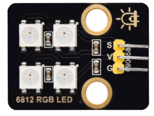
The RGB LED 6812 is a type of addressable LED that integrates red, green, and blue diodes into a single package. This component allows for precise control of color and brightness through digital signals, enabling the creation of a wide range of colors and dynamic lighting effects. Each LED in the 6812 series has an integrated driver chip, which simplifies control and allows multiple LEDs to be daisy-chained for complex lighting setups.

Explore Projects Built with RGB LED 6812

Use Cirkit Designer to design, explore, and prototype these projects online. Some projects support real-time simulation. Click "Open Project" to start designing instantly!
Battery-Powered RGB LED Control with Pushbuttons
Image of EXP-12 E: A project utilizing RGB LED 6812 in a practical application
This circuit consists of an RGB LED controlled by three pushbuttons, each corresponding to one of the LED's color channels (Red, Green, and Blue). The pushbuttons are powered by a MAHIR 1.mini power source, allowing the user to manually toggle each color channel of the RGB LED.
Cirkit Designer LogoOpen Project in Cirkit Designer
Interactive RGB LED Control Circuit with Pushbuttons
Image of rgb circuit: A project utilizing RGB LED 6812 in a practical application
This circuit features a 9V battery connected to a voltage regulator, which likely steps down the voltage to a lower level suitable for driving an RGB LED. Three pushbuttons are connected to the output of the voltage regulator, each controlling one color channel (red, green, and blue) of the RGB LED. A resistor is connected in series with the common cathode of the RGB LED to limit the current through the LED.
Cirkit Designer LogoOpen Project in Cirkit Designer
Arduino Nano-Controlled Lighting System with Gesture and Sound Interaction
Image of 4 load controll using hand gesture and sound controll: A project utilizing RGB LED 6812 in a practical application
This circuit features an Arduino Nano microcontroller interfaced with an APDS-9960 RGB and Gesture Sensor for color and gesture detection, and a KY-038 microphone module for sound detection. The Arduino controls a 4-channel relay module, which in turn switches four AC bulbs on and off. The 12V power supply is used to power the relay module, and the bulbs are connected to the normally open (N.O.) contacts of the relays, allowing the Arduino to control the lighting based on sensor inputs.
Cirkit Designer LogoOpen Project in Cirkit Designer
ESP32-Controlled RGB LED Lighting System
Image of RGBLEDwithFlutterFirebase: A project utilizing RGB LED 6812 in a practical application
This circuit features an ESP32 microcontroller connected to an RGB LED through three 200 Ohm resistors. Each color channel (Red, Green, Blue) of the LED is connected to a GPIO pin (G13, G12, G14 respectively) on the ESP32 via a resistor. The common anode of the RGB LED is directly connected to the 3.3V power supply from the ESP32, allowing the microcontroller to control the color of the LED by PWM signals on the GPIO pins.
Cirkit Designer LogoOpen Project in Cirkit Designer

Explore Projects Built with RGB LED 6812

Use Cirkit Designer to design, explore, and prototype these projects online. Some projects support real-time simulation. Click "Open Project" to start designing instantly!
Image of EXP-12 E: A project utilizing RGB LED 6812 in a practical application
Battery-Powered RGB LED Control with Pushbuttons
This circuit consists of an RGB LED controlled by three pushbuttons, each corresponding to one of the LED's color channels (Red, Green, and Blue). The pushbuttons are powered by a MAHIR 1.mini power source, allowing the user to manually toggle each color channel of the RGB LED.
Cirkit Designer LogoOpen Project in Cirkit Designer
Image of rgb circuit: A project utilizing RGB LED 6812 in a practical application
Interactive RGB LED Control Circuit with Pushbuttons
This circuit features a 9V battery connected to a voltage regulator, which likely steps down the voltage to a lower level suitable for driving an RGB LED. Three pushbuttons are connected to the output of the voltage regulator, each controlling one color channel (red, green, and blue) of the RGB LED. A resistor is connected in series with the common cathode of the RGB LED to limit the current through the LED.
Cirkit Designer LogoOpen Project in Cirkit Designer
Image of 4 load controll using hand gesture and sound controll: A project utilizing RGB LED 6812 in a practical application
Arduino Nano-Controlled Lighting System with Gesture and Sound Interaction
This circuit features an Arduino Nano microcontroller interfaced with an APDS-9960 RGB and Gesture Sensor for color and gesture detection, and a KY-038 microphone module for sound detection. The Arduino controls a 4-channel relay module, which in turn switches four AC bulbs on and off. The 12V power supply is used to power the relay module, and the bulbs are connected to the normally open (N.O.) contacts of the relays, allowing the Arduino to control the lighting based on sensor inputs.
Cirkit Designer LogoOpen Project in Cirkit Designer
Image of RGBLEDwithFlutterFirebase: A project utilizing RGB LED 6812 in a practical application
ESP32-Controlled RGB LED Lighting System
This circuit features an ESP32 microcontroller connected to an RGB LED through three 200 Ohm resistors. Each color channel (Red, Green, Blue) of the LED is connected to a GPIO pin (G13, G12, G14 respectively) on the ESP32 via a resistor. The common anode of the RGB LED is directly connected to the 3.3V power supply from the ESP32, allowing the microcontroller to control the color of the LED by PWM signals on the GPIO pins.
Cirkit Designer LogoOpen Project in Cirkit Designer

Common Applications

  • Decorative lighting and LED strips
  • Digital displays and signage
  • Wearable electronics
  • Gaming peripherals and RGB keyboards
  • Art installations and interactive projects

Technical Specifications

The RGB LED 6812 is designed for ease of use and high performance. Below are its key technical details:

Parameter Value
Operating Voltage 3.3V to 5.5V
Operating Current ~18mA per color channel (max)
Communication Protocol Single-wire digital control
LED Colors Red, Green, Blue (24-bit color)
Brightness Levels 256 levels per color channel
Data Speed Up to 800 kHz
Viewing Angle ~120°
Package Type 6812 (SMD)

Pin Configuration

The RGB LED 6812 typically has four pins. Below is the pinout description:

Pin Name Description
VDD Power supply pin (3.3V to 5.5V)
GND Ground connection
DIN Data input pin for receiving control signals
DOUT Data output pin for chaining additional LEDs

Usage Instructions

How to Use the RGB LED 6812 in a Circuit

  1. Power Supply: Connect the VDD pin to a 3.3V or 5V power source and the GND pin to ground. Ensure the power supply can handle the total current draw of all connected LEDs.
  2. Data Input: Use a microcontroller (e.g., Arduino) to send digital control signals to the DIN pin. A resistor (330-500 ohms) is recommended between the microcontroller's data pin and the DIN pin to reduce noise.
  3. Chaining LEDs: Connect the DOUT pin of one LED to the DIN pin of the next LED to create a chain. Ensure all LEDs share the same power and ground connections.
  4. Decoupling Capacitor: Place a 0.1µF capacitor between VDD and GND for each LED to stabilize the power supply.

Important Considerations

  • Voltage Levels: Ensure the data signal voltage matches the LED's operating voltage. If using a 3.3V microcontroller with a 5V LED, a level shifter may be required.
  • Heat Management: Avoid exceeding the maximum current rating to prevent overheating. Use proper heat dissipation techniques for large arrays.
  • Data Timing: Follow the timing requirements specified in the datasheet for reliable communication.

Example Code for Arduino UNO

Below is an example of how to control an RGB LED 6812 using the Arduino UNO and the Adafruit NeoPixel library:

#include <Adafruit_NeoPixel.h>

// Define the pin connected to the DIN pin of the RGB LED
#define LED_PIN 6

// Define the number of LEDs in the chain
#define NUM_LEDS 1

// Create a NeoPixel object
Adafruit_NeoPixel strip = Adafruit_NeoPixel(NUM_LEDS, LED_PIN, NEO_GRB + NEO_KHZ800);

void setup() {
  strip.begin(); // Initialize the NeoPixel library
  strip.show();  // Turn off all LEDs initially
}

void loop() {
  // Set the first LED to red
  strip.setPixelColor(0, strip.Color(255, 0, 0)); // Red: 255, Green: 0, Blue: 0
  strip.show(); // Update the LED to display the color
  delay(1000);  // Wait for 1 second

  // Set the first LED to green
  strip.setPixelColor(0, strip.Color(0, 255, 0)); // Red: 0, Green: 255, Blue: 0
  strip.show(); // Update the LED to display the color
  delay(1000);  // Wait for 1 second

  // Set the first LED to blue
  strip.setPixelColor(0, strip.Color(0, 0, 255)); // Red: 0, Green: 0, Blue: 255
  strip.show(); // Update the LED to display the color
  delay(1000);  // Wait for 1 second
}

Troubleshooting and FAQs

Common Issues

  1. LEDs Not Lighting Up

    • Cause: Incorrect wiring or insufficient power supply.
    • Solution: Double-check all connections, ensure the power supply meets the voltage and current requirements, and verify the data pin connection.
  2. Flickering or Unstable Colors

    • Cause: Noise in the data line or insufficient decoupling.
    • Solution: Add a resistor (330-500 ohms) to the data line and a 0.1µF capacitor between VDD and GND for each LED.
  3. Incorrect Colors Displayed

    • Cause: Data timing mismatch or incorrect library settings.
    • Solution: Verify the microcontroller's timing and ensure the correct LED type (e.g., NEO_GRB) is specified in the code.
  4. Chained LEDs Not Responding

    • Cause: Faulty connections between DOUT and DIN pins.
    • Solution: Check the connections between LEDs and ensure proper soldering or wiring.

FAQs

  • Can I control the RGB LED 6812 without a library? Yes, but it requires precise timing to send data signals. Using a library like Adafruit NeoPixel simplifies the process.

  • What is the maximum number of LEDs I can chain? Theoretically, there is no limit, but practical constraints like power supply capacity and signal integrity must be considered.

  • Do I need a separate resistor for each LED? No, a single resistor on the data line is sufficient for the entire chain.

By following this documentation, you can effectively integrate and troubleshoot the RGB LED 6812 in your projects.