How to Use Adafruit 16-Channel PWM + Servo HAT: Examples, Pinouts, and Specs
Introduction
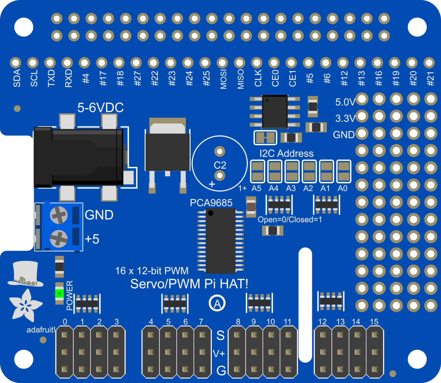
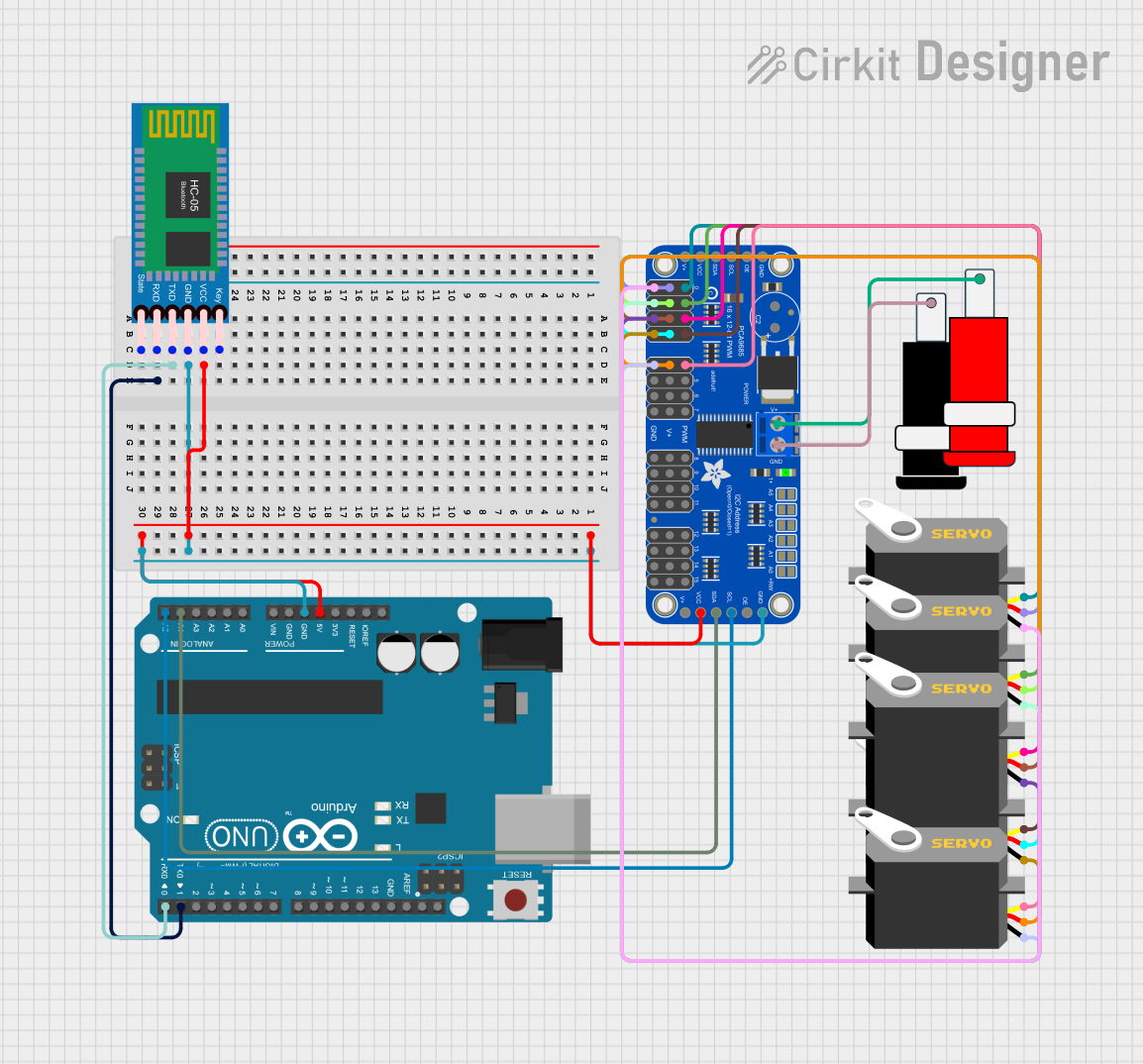
The Adafruit 16-Channel PWM + Servo HAT is an add-on board for the Raspberry Pi designed to drive up to 16 servos with precise Pulse Width Modulation (PWM) signals. It is an ideal solution for robotics, animatronics, and automation projects where multiple servos or PWM outputs are required. The HAT also includes additional PWM channels that can be used for dimming LEDs or controlling other devices that accept PWM signals.
Explore Projects Built with Adafruit 16-Channel PWM + Servo HAT
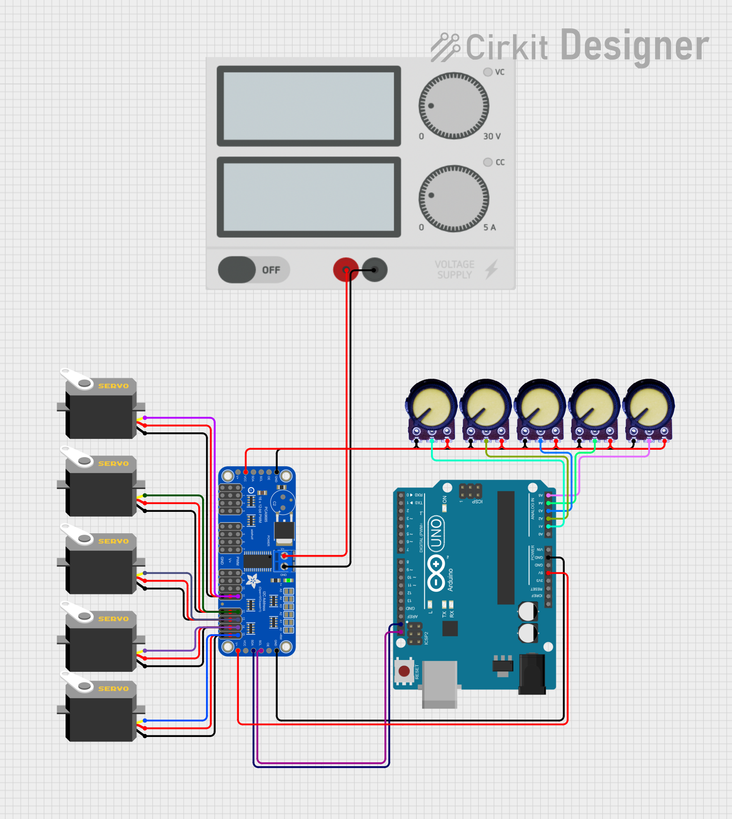
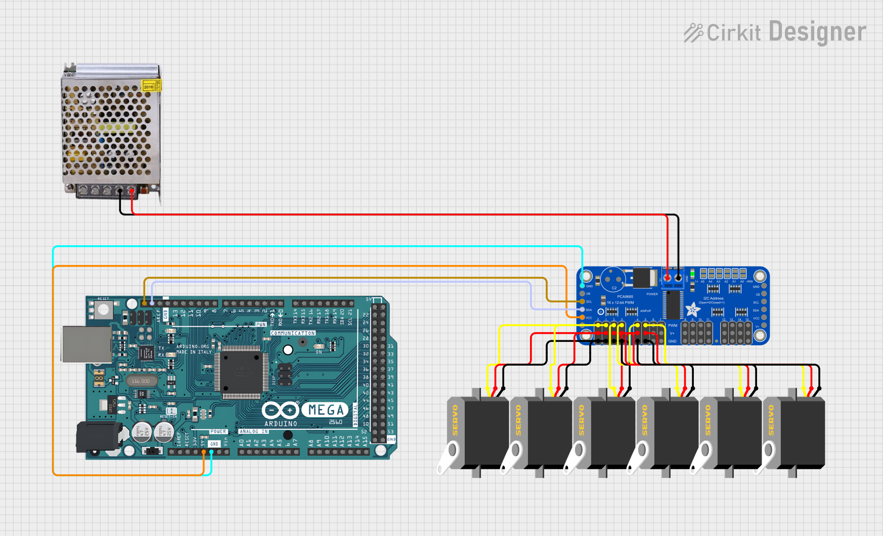
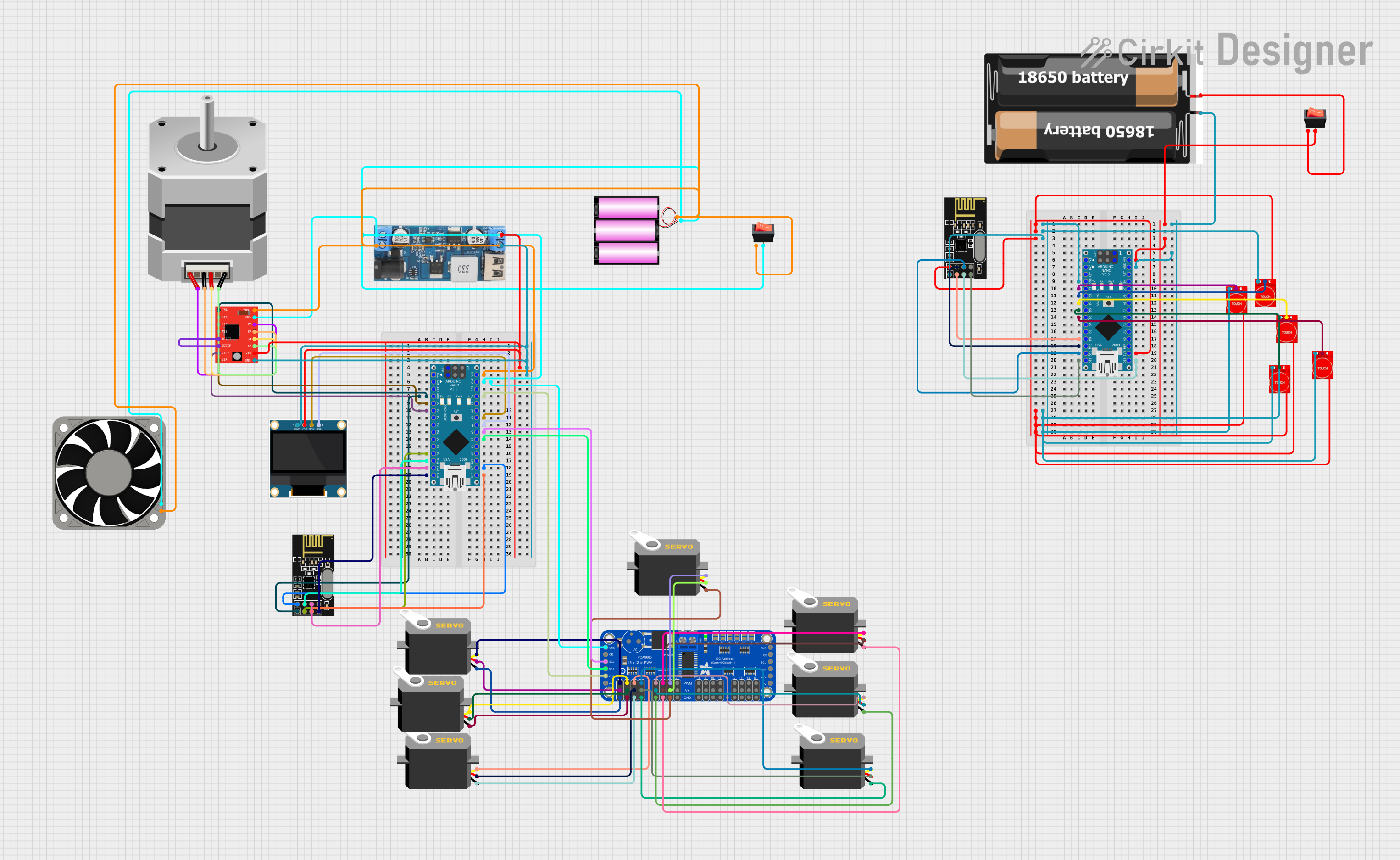
Explore Projects Built with Adafruit 16-Channel PWM + Servo HAT
Common Applications and Use Cases
- Robotics: Control multiple servo motors for robotic arms, walkers, or drones.
- Animatronics: Bring sculptures or costumes to life with multiple moving parts.
- Lighting control: Manage brightness levels of LED arrays.
- Home automation: Integrate with home automation systems for controlling blinds, fans, or other PWM-driven devices.
Technical Specifications
Key Technical Details
- Voltage: 5V (supplied by the Raspberry Pi)
- Channels: 16 PWM/Servo channels
- Frequency: 40-1000 Hz adjustable PWM frequency
- Resolution: 12-bit, 4096 steps for each PWM output
- Communication: I2C interface
- Dimensions: 65mm x 56mm x 13mm
Pin Configuration and Descriptions
| Pin Number | Description | Notes |
|---|---|---|
| 1-16 | PWM/Servo Output Channels | Connect to servo or PWM device |
| SDA | I2C Data | Connects to the Pi's I2C SDA |
| SCL | I2C Clock | Connects to the Pi's I2C SCL |
| 5V | Power Supply for Servos | Provided by external source |
| GND | Ground | Common ground for logic & power |
Usage Instructions
How to Use the Component in a Circuit
- Attach the HAT to the Raspberry Pi GPIO header. Ensure the Pi is powered off before attaching the HAT.
- Connect an external 5V power supply to the HAT to power the servos. Do not power high-torque servos directly from the Pi.
- Connect the servos to the PWM output channels. Pay attention to the polarity of the servo connectors.
- Install the necessary software libraries to control the HAT from the Raspberry Pi.
Important Considerations and Best Practices
- Always use an external power supply for the servos to prevent overloading the Raspberry Pi's power supply.
- Ensure that the ground of the external power supply is connected to the ground of the Raspberry Pi.
- Avoid disconnecting or connecting servos while the HAT is powered to prevent damage.
- Use proper ESD precautions when handling the HAT to avoid static damage to the electronics.
Example Code for Raspberry Pi
Here is a simple Python script to control a servo connected to channel 0 of the Adafruit 16-Channel PWM + Servo HAT:
import Adafruit_PCA9685
Initialize the PCA9685 using the default address (0x40).
pwm = Adafruit_PCA9685.PCA9685()
Configure min and max servo pulse lengths
servo_min = 150 # Min pulse length out of 4096 servo_max = 600 # Max pulse length out of 4096
Helper function to make setting a servo pulse width simpler.
def set_servo_pulse(channel, pulse): pulse_length = 1000000 # 1,000,000 us per second pulse_length //= 60 # 60 Hz print('{0}us per period'.format(pulse_length)) pulse_length //= 4096 # 12 bits of resolution print('{0}us per bit'.format(pulse_length)) pulse *= 1000 pulse //= pulse_length pwm.set_pwm(channel, 0, pulse)
Set frequency to 60hz, good for servos.
pwm.set_pwm_freq(60)
Set servo to the neutral position on channel 0
pwm.set_pwm(0, 0, (servo_min + servo_max) // 2)
Remember to install the Adafruit_PCA9685 library before running the script:

```shell
sudo pip install adafruit-pca9685
Troubleshooting and FAQs
Common Issues
- Servos not responding: Ensure that the external power supply is correctly connected and turned on.
- Inaccurate servo movement: Check if the servo_min and servo_max values are correctly calibrated for your specific servo model.
- I2C communication errors: Make sure the HAT is properly seated on the Pi and that no pins are bent or missing.
Solutions and Tips for Troubleshooting
- Double-check wiring, especially the power supply connections.
- Use
i2cdetect -y 1to verify that the Raspberry Pi is detecting the HAT. - Review the Raspberry Pi's power supply capability if you're using low-power servos that don't require an external power source.
FAQs
Q: Can I stack multiple HATs to control more than 16 servos? A: Yes, you can stack up to 62 HATs for controlling up to 992 PWM outputs, but you'll need to configure different I2C addresses for each HAT.
Q: Do I need to install a heatsink on the HAT? A: Under normal usage with servos, a heatsink is not required. However, if you're using the HAT to drive a large number of LEDs or other high-current devices, additional cooling may be necessary.
Q: Can I use this HAT with other single-board computers or microcontrollers? A: Yes, as long as the device supports I2C communication and can interface with the HAT's logic level, it can be used with other boards.