How to Use ph 4502c: Examples, Pinouts, and Specs
Introduction
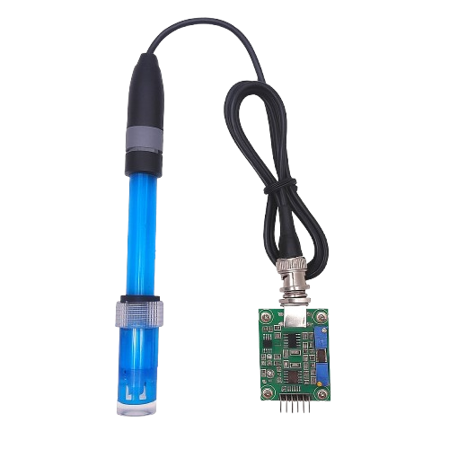
The PH 4502C is a high-performance operational amplifier (op-amp) designed for precision applications. It features low noise, high gain bandwidth, and excellent stability, making it ideal for signal conditioning, amplification, and other analog processing tasks. This component is widely used in instrumentation, audio processing, sensor interfacing, and other circuits requiring accurate signal amplification.
Explore Projects Built with ph 4502c
Explore Projects Built with ph 4502c
Common Applications:
- Signal conditioning for sensors (e.g., temperature, pressure, or pH sensors)
- Audio preamplifiers and equalizers
- Analog computation and filtering
- Precision voltage and current measurement
- Data acquisition systems
Technical Specifications
Below are the key technical details of the PH 4502C operational amplifier:
| Parameter | Value |
|---|---|
| Supply Voltage Range | ±3V to ±18V |
| Input Offset Voltage | ≤ 2 mV |
| Input Bias Current | ≤ 50 nA |
| Gain Bandwidth Product | 10 MHz |
| Slew Rate | 0.5 V/µs |
| Input Impedance | ≥ 10 MΩ |
| Output Impedance | ≤ 100 Ω |
| Operating Temperature Range | -40°C to +85°C |
| Package Type | DIP-8 or SOIC-8 |
Pin Configuration
The PH 4502C is typically available in an 8-pin DIP or SOIC package. Below is the pinout and description:
| Pin Number | Pin Name | Description |
|---|---|---|
| 1 | Offset Null | Used for offset voltage adjustment (optional) |
| 2 | Inverting Input (-) | Input for the inverting signal |
| 3 | Non-Inverting Input (+) | Input for the non-inverting signal |
| 4 | V- (GND) | Negative power supply or ground |
| 5 | Offset Null | Used for offset voltage adjustment (optional) |
| 6 | Output | Amplified output signal |
| 7 | V+ | Positive power supply |
| 8 | NC (No Connect) | Not connected internally (varies by package) |
Usage Instructions
How to Use the PH 4502C in a Circuit
- Power Supply: Connect the V+ pin (Pin 7) to the positive supply voltage and the V- pin (Pin 4) to the negative supply voltage or ground, depending on your circuit design.
- Input Signals: Feed the input signal to either the inverting input (Pin 2) or the non-inverting input (Pin 3), depending on the desired configuration:
- Inverting Configuration: The input signal is applied to Pin 2, and Pin 3 is connected to a reference voltage (e.g., ground).
- Non-Inverting Configuration: The input signal is applied to Pin 3, and Pin 2 is connected to a feedback network.
- Feedback Network: Use resistors or other components to set the gain and stability of the amplifier. For example:
- Gain = 1 + (Rf / Rin), where Rf is the feedback resistor and Rin is the input resistor.
- Output Signal: The amplified signal is available at the output pin (Pin 6). Ensure the load impedance is compatible with the op-amp's output drive capability.
Important Considerations
- Power Supply Decoupling: Place decoupling capacitors (e.g., 0.1 µF ceramic and 10 µF electrolytic) close to the power supply pins to reduce noise and improve stability.
- Offset Adjustment: If precise offset voltage adjustment is required, connect a 10 kΩ potentiometer between the Offset Null pins (Pins 1 and 5) and tie the wiper to V+.
- Avoid Overloading: Ensure the output current does not exceed the op-amp's maximum rating to prevent damage.
- Temperature Effects: Operate the component within the specified temperature range to maintain performance.
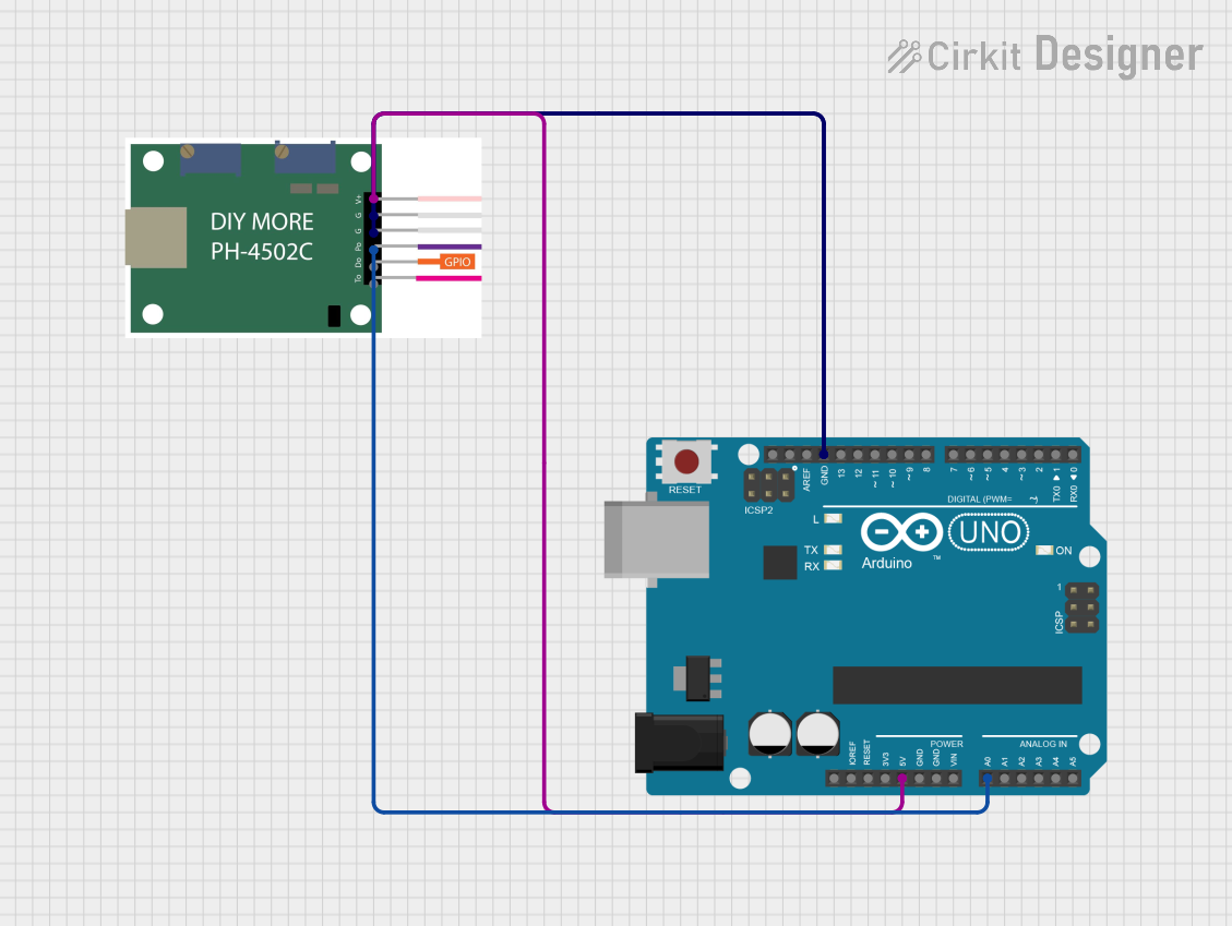
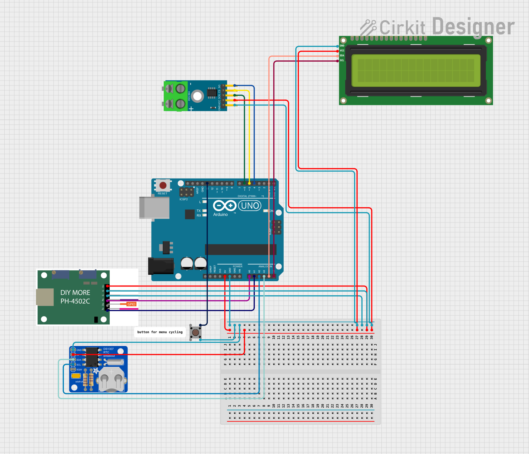
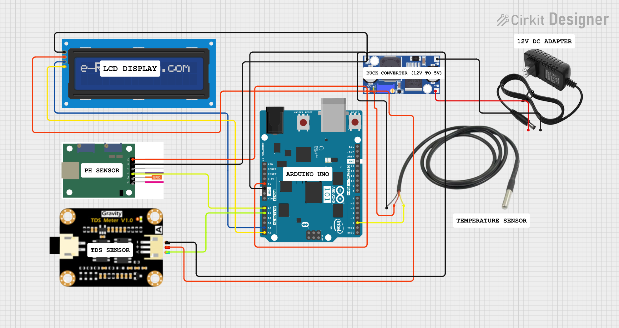
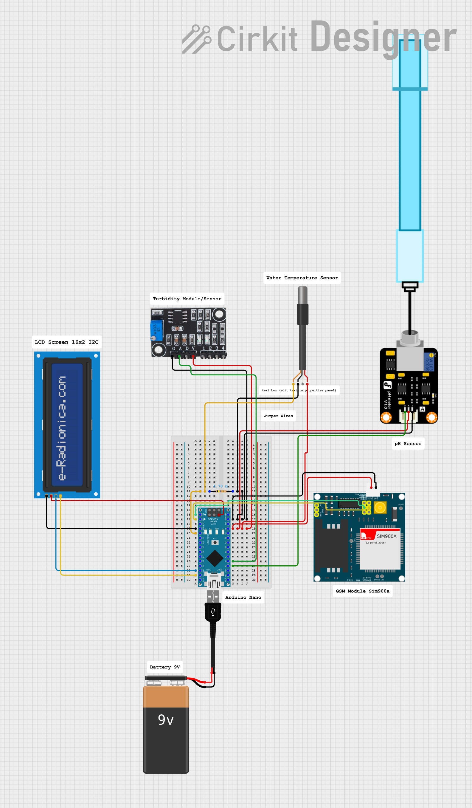
Example: Connecting the PH 4502C to an Arduino UNO
The PH 4502C can be used to amplify signals from a sensor before feeding them into an Arduino's analog input. Below is an example circuit and code for reading a pH sensor signal:
Circuit:
- Connect the pH sensor output to the non-inverting input (Pin 3) of the PH 4502C.
- Use a feedback resistor (Rf) and input resistor (Rin) to set the desired gain.
- Connect the output (Pin 6) of the PH 4502C to an analog input pin (e.g., A0) on the Arduino UNO.
Arduino Code:
// Arduino code to read amplified pH sensor signal using PH 4502C
const int analogPin = A0;  // Analog pin connected to PH 4502C output
float voltage = 0.0;       // Variable to store the measured voltage
float pH = 0.0;            // Variable to store the calculated pH value

void setup() {
  Serial.begin(9600);  // Initialize serial communication
}

void loop() {
  int sensorValue = analogRead(analogPin);  // Read analog value (0-1023)

  // Convert the analog value to voltage (assuming 5V reference)
  voltage = sensorValue * (5.0 / 1023.0);

  // Convert voltage to pH (example formula, adjust based on calibration)
  pH = 7.0 + ((voltage - 2.5) / 0.18);  // Example: 2.5V = pH 7, 0.18V per pH unit

  // Print the results to the Serial Monitor
  Serial.print("Voltage: ");
  Serial.print(voltage);
  Serial.print(" V, pH: ");
  Serial.println(pH);

  delay(1000);  // Wait 1 second before the next reading
}
Troubleshooting and FAQs
Common Issues and Solutions
No Output Signal:
- Check the power supply connections (V+ and V-).
- Verify that the input signal is within the op-amp's input voltage range.
- Ensure the feedback network is properly connected.
Output Signal is Distorted:
- Verify that the load impedance is not too low for the op-amp to drive.
- Check for proper decoupling capacitors near the power supply pins.
Incorrect Gain:
- Double-check the resistor values in the feedback network.
- Ensure the resistors are connected correctly.
High Noise in Output:
- Use shielded cables for input signals.
- Add bypass capacitors to reduce noise.
FAQs
Q: Can the PH 4502C operate with a single power supply?
A: Yes, the PH 4502C can operate with a single supply, but the input and output signals must be biased appropriately to stay within the op-amp's operating range.
Q: What is the maximum output current of the PH 4502C?
A: The maximum output current is typically around 20 mA. Exceeding this limit may damage the component.
Q: How do I calibrate the pH sensor with the PH 4502C?
A: Use a known pH buffer solution and adjust the offset or gain (if adjustable) to match the expected output voltage for the given pH value.