How to Use Placa_Controladora: Examples, Pinouts, and Specs
Introduction
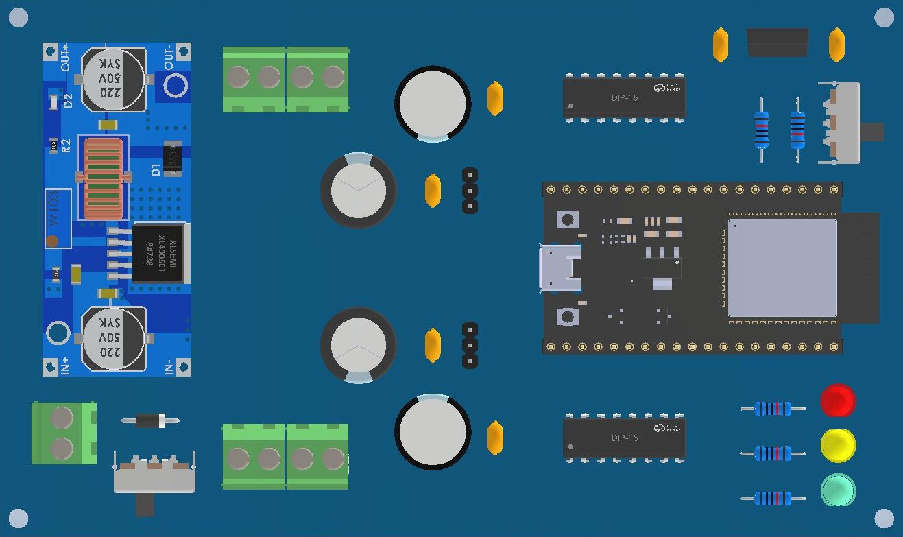
The Placa_Controladora is a versatile control board designed to manage and coordinate the operation of various electronic components in a circuit. It serves as the central hub for automation and robotics projects, enabling seamless communication between sensors, actuators, and other peripherals. With its robust design and compatibility with a wide range of devices, the Placa_Controladora is ideal for both hobbyists and professionals working on complex electronic systems.
Explore Projects Built with Placa_Controladora

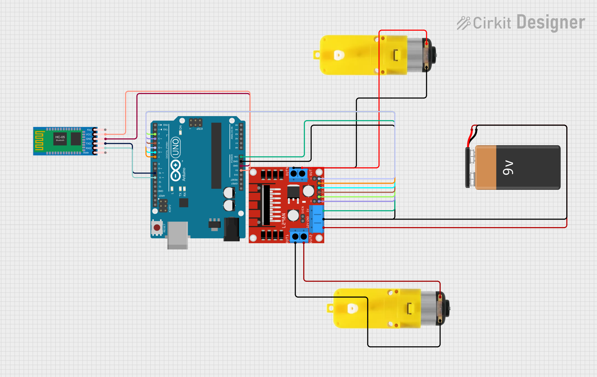
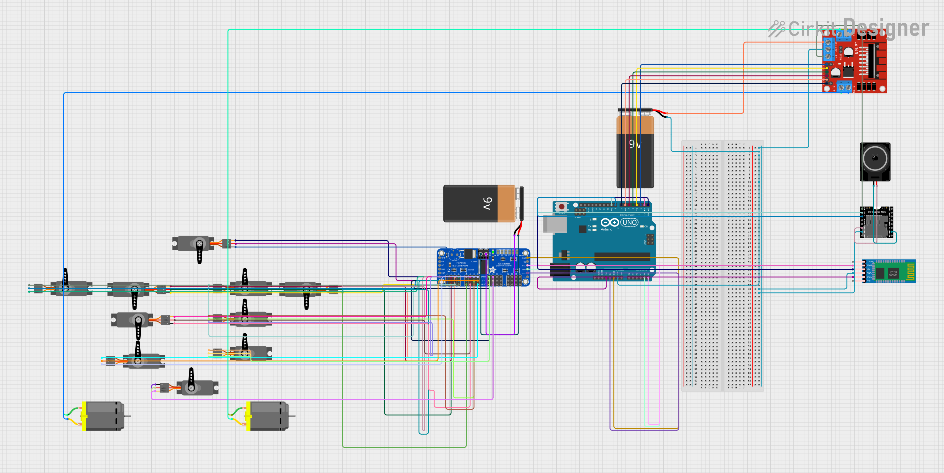
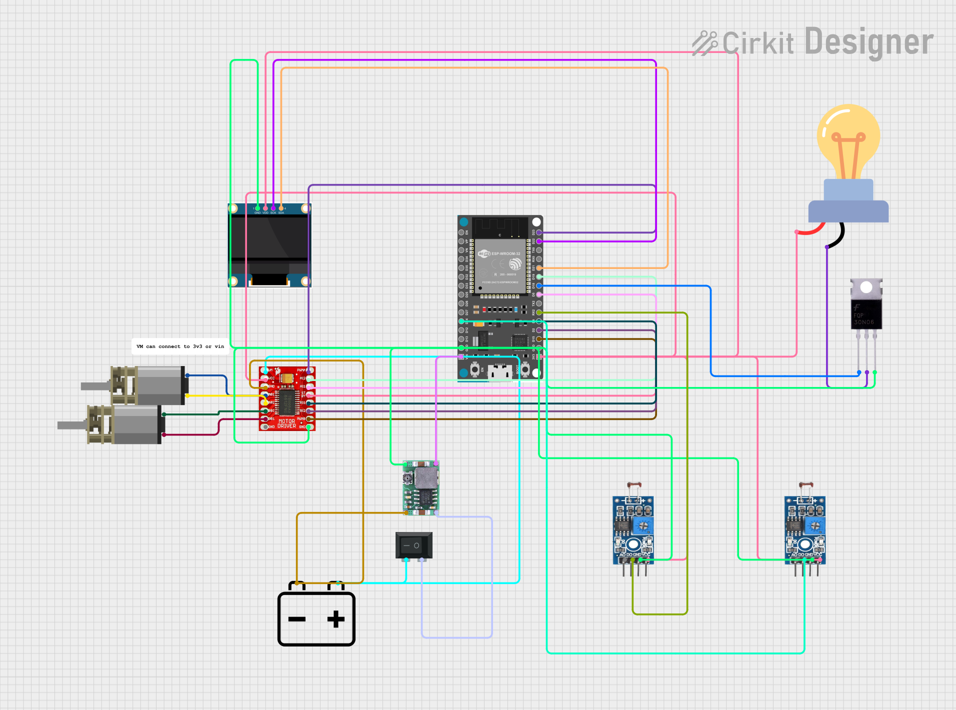
Explore Projects Built with Placa_Controladora
Common Applications and Use Cases
- Robotics: Controlling motors, servos, and sensors in robotic systems.
- Home Automation: Managing smart devices and sensors for automated tasks.
- Industrial Automation: Coordinating machinery and processes in manufacturing.
- IoT Projects: Acting as a central controller for connected devices.
- Educational Projects: Teaching electronics and programming concepts.
Technical Specifications
The Placa_Controladora is designed to provide reliable performance in a variety of applications. Below are its key technical details:
General Specifications
| Parameter | Value |
|---|---|
| Operating Voltage | 5V DC |
| Input Voltage Range | 7V - 12V DC |
| Maximum Current Output | 1A per pin (total 10A max) |
| Communication Protocols | UART, I2C, SPI |
| Microcontroller | ATmega328P or equivalent |
| Clock Speed | 16 MHz |
| Digital I/O Pins | 14 (6 PWM capable) |
| Analog Input Pins | 6 |
| Dimensions | 68.6 mm x 53.4 mm |
Pin Configuration and Descriptions
| Pin Name | Type | Description |
|---|---|---|
| VIN | Power Input | External power input (7V-12V DC). |
| GND | Ground | Common ground for the circuit. |
| 5V | Power Output | Regulated 5V output for powering external components. |
| 3.3V | Power Output | Regulated 3.3V output for low-power devices. |
| Digital Pins | I/O | 14 digital pins for input/output operations (6 support PWM). |
| Analog Pins | Input | 6 analog input pins for reading sensor data (0-5V range). |
| TX/RX | UART | Serial communication pins for transmitting (TX) and receiving (RX) data. |
| SCL/SDA | I2C | Clock (SCL) and data (SDA) lines for I2C communication. |
| SPI Pins | Communication | MOSI, MISO, and SCK pins for SPI communication. |
| RESET | Reset | Resets the microcontroller. |
Usage Instructions
The Placa_Controladora is straightforward to use in a variety of circuits. Follow the steps below to integrate it into your project:
Step 1: Powering the Board
- Connect an external power source to the VIN pin (7V-12V DC) or use the USB port if available.
- Ensure the power supply is stable and within the specified voltage range to avoid damage.
Step 2: Connecting Components
- Use the Digital I/O Pins to connect actuators like motors, LEDs, or relays.
- Connect sensors to the Analog Input Pins for reading environmental data.
- For communication with other devices, use the UART (TX/RX), I2C (SCL/SDA), or SPI pins.
Step 3: Programming the Board
- The Placa_Controladora is compatible with the Arduino IDE. Install the necessary drivers and select the correct board type (e.g., Arduino Uno if using ATmega328P).
- Write your program in the Arduino IDE and upload it to the board via USB.
Example Code: Blinking an LED
Below is an example of how to blink an LED connected to a digital pin:
// Define the pin number where the LED is connected
const int ledPin = 13;

void setup() {
  // Set the LED pin as an output
  pinMode(ledPin, OUTPUT);
}

void loop() {
  // Turn the LED on
  digitalWrite(ledPin, HIGH);
  delay(1000); // Wait for 1 second

  // Turn the LED off
  digitalWrite(ledPin, LOW);
  delay(1000); // Wait for 1 second
}
Best Practices
- Always double-check connections to avoid short circuits or incorrect wiring.
- Use appropriate resistors for LEDs and other components to prevent overcurrent.
- Avoid exceeding the maximum current output of the board (1A per pin, 10A total).
Troubleshooting and FAQs
Common Issues and Solutions
The board does not power on.
- Ensure the power supply is within the 7V-12V range.
- Check the connections to the VIN and GND pins.
Components are not responding.
- Verify that the components are connected to the correct pins.
- Check the program code for errors or incorrect pin assignments.
The board overheats.
- Ensure the total current draw does not exceed 10A.
- Use a heat sink or cooling fan if necessary.
Unable to upload code.
- Confirm that the correct board and port are selected in the Arduino IDE.
- Check the USB cable and connection.
FAQs
Q: Can I use the Placa_Controladora with 3.3V sensors?
A: Yes, the board provides a 3.3V output pin for low-power devices.
Q: Is the board compatible with shields?
A: Yes, the Placa_Controladora is compatible with most Arduino Uno shields.
Q: What is the maximum PWM frequency?
A: The default PWM frequency is approximately 490 Hz, but it can be adjusted in the code.
By following this documentation, you can effectively use the Placa_Controladora in your projects and troubleshoot common issues with ease.