How to Use FAN 12V: Examples, Pinouts, and Specs
Introduction
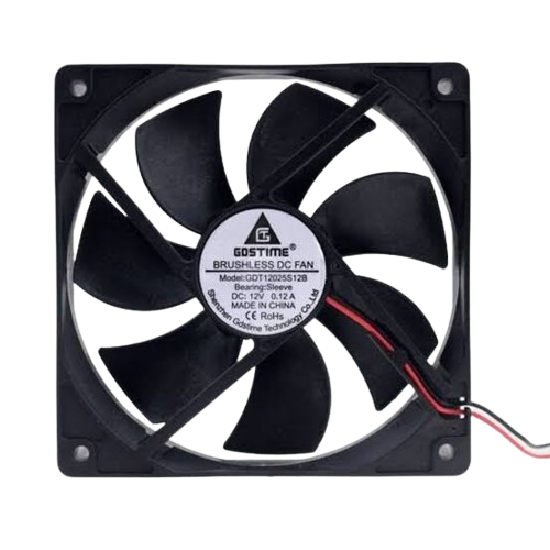
A 12V fan is an electric fan designed to operate at a voltage of 12 volts. It is widely used for cooling electronic devices, improving airflow in enclosures, or providing ventilation in various applications. These fans are compact, efficient, and reliable, making them a popular choice in computer systems, power supplies, and other electronic equipment where heat dissipation is critical.
Explore Projects Built with FAN 12V


Explore Projects Built with FAN 12V
Common Applications and Use Cases
- Cooling computer components such as CPUs, GPUs, and power supplies.
- Ventilation in enclosures, cabinets, or small rooms.
- Heat dissipation in industrial equipment and machinery.
- Airflow management in DIY electronics projects.
- Cooling for 3D printers and other hobbyist applications.
Technical Specifications
Below are the key technical details for a standard 12V fan:
| Parameter | Specification |
|---|---|
| Operating Voltage | 12V DC |
| Current Consumption | 0.1A to 0.5A (varies by model) |
| Power Consumption | 1.2W to 6W |
| Fan Speed | 2000 to 5000 RPM (varies by model) |
| Airflow | 20 to 80 CFM (Cubic Feet per Minute) |
| Noise Level | 20 to 40 dBA |
| Connector Type | 2-pin, 3-pin, or 4-pin |
| Dimensions | Common sizes: 40mm, 60mm, 80mm, 120mm |
| Bearing Type | Sleeve or Ball Bearing |
| Lifespan | 30,000 to 50,000 hours |
Pin Configuration and Descriptions
The pin configuration depends on the type of connector used. Below are the details for common configurations:
2-Pin Connector
| Pin Number | Name | Description |
|---|---|---|
| 1 | VCC (+12V) | Positive power supply terminal |
| 2 | GND | Ground terminal |
3-Pin Connector
| Pin Number | Name | Description |
|---|---|---|
| 1 | VCC (+12V) | Positive power supply terminal |
| 2 | GND | Ground terminal |
| 3 | Tachometer | Outputs fan speed signal (RPM) |
4-Pin Connector (PWM Control)
| Pin Number | Name | Description |
|---|---|---|
| 1 | VCC (+12V) | Positive power supply terminal |
| 2 | GND | Ground terminal |
| 3 | Tachometer | Outputs fan speed signal (RPM) |
| 4 | PWM | Pulse Width Modulation control |
Usage Instructions
How to Use the Component in a Circuit
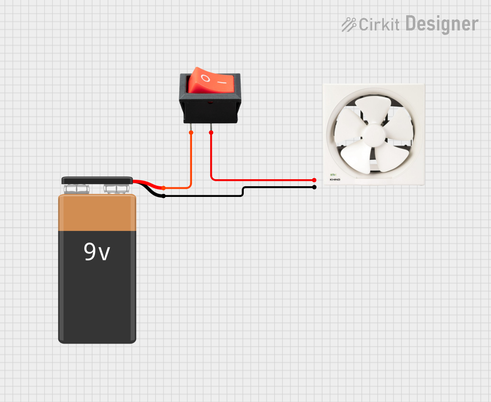
- Power Supply: Connect the VCC pin to a 12V DC power source and the GND pin to ground.
- Fan Speed Control:
- For 2-pin fans, speed is fixed and depends on the supplied voltage.
- For 3-pin fans, you can monitor the speed using the tachometer pin.
- For 4-pin fans, use the PWM pin to control the fan speed programmatically.
- Mounting: Secure the fan in place using screws or adhesive mounts. Ensure proper airflow direction by checking the fan's markings (airflow direction is usually indicated by arrows on the fan housing).
Important Considerations and Best Practices
- Voltage Compatibility: Ensure the power supply provides a stable 12V DC output. Overvoltage can damage the fan.
- Current Rating: Verify that the power supply can handle the fan's current requirements.
- Airflow Direction: Install the fan so that it directs airflow in the desired direction. Most fans have arrows indicating airflow and blade rotation.
- Noise Reduction: Use rubber mounts or grommets to minimize vibration and noise.
- PWM Control: For 4-pin fans, use a microcontroller (e.g., Arduino) to adjust the fan speed via PWM.
Example: Controlling a 4-Pin 12V Fan with Arduino UNO
Below is an example of how to control a 4-pin 12V fan using an Arduino UNO:
// Example: Controlling a 4-pin 12V fan with Arduino UNO
// Connect the fan's PWM pin to Arduino pin 9
// Ensure the fan's VCC and GND are connected to a 12V power source

const int pwmPin = 9; // PWM pin connected to the fan's PWM input

void setup() {
  pinMode(pwmPin, OUTPUT); // Set the PWM pin as an output
}

void loop() {
  // Set fan speed to 50% (128 out of 255)
  analogWrite(pwmPin, 128);
  delay(5000); // Run at 50% speed for 5 seconds

  // Set fan speed to 100% (255 out of 255)
  analogWrite(pwmPin, 255);
  delay(5000); // Run at full speed for 5 seconds

  // Set fan speed to 0% (fan off)
  analogWrite(pwmPin, 0);
  delay(5000); // Turn off the fan for 5 seconds
}
Troubleshooting and FAQs
Common Issues and Solutions
Fan Does Not Spin:
- Cause: No power or incorrect wiring.
- Solution: Verify the power supply voltage and ensure proper connections to VCC and GND.
Fan Spins Slowly:
- Cause: Insufficient voltage or high resistance in the circuit.
- Solution: Check the power supply and ensure it provides a stable 12V output.
Excessive Noise:
- Cause: Vibration or worn-out bearings.
- Solution: Use rubber mounts to reduce vibration or replace the fan if bearings are damaged.
PWM Control Not Working:
- Cause: Incorrect PWM signal or wiring.
- Solution: Ensure the PWM pin is connected to the correct microcontroller pin and verify the PWM signal frequency (typically 25kHz for most fans).
FAQs
Q: Can I use a 12V fan with a 5V power supply?
A: No, a 12V fan requires a 12V power supply to operate correctly. Using a lower voltage will result in reduced performance or failure to spin.
Q: How do I determine the airflow direction?
A: Most fans have arrows on the housing indicating the airflow direction and blade rotation.
Q: Can I connect a 12V fan directly to an Arduino?
A: No, the Arduino cannot supply sufficient current or voltage for a 12V fan. Use an external 12V power supply and a transistor or MOSFET for control.
Q: What is the typical lifespan of a 12V fan?
A: The lifespan varies by model and usage but is typically between 30,000 and 50,000 hours.