How to Use Touch Sensor TTP233: Examples, Pinouts, and Specs
Introduction
The Touch Sensor TTP233 is a capacitive touch switch module designed by Adafruit. This sensor is capable of detecting touch or proximity with a simple tap or swipe of a finger. It is widely used in various applications such as interactive installations, user interfaces, and any project where touch sensing is required. The TTP233 is a versatile and reliable component that can add intuitive touch controls to your electronic projects.
Explore Projects Built with Touch Sensor TTP233
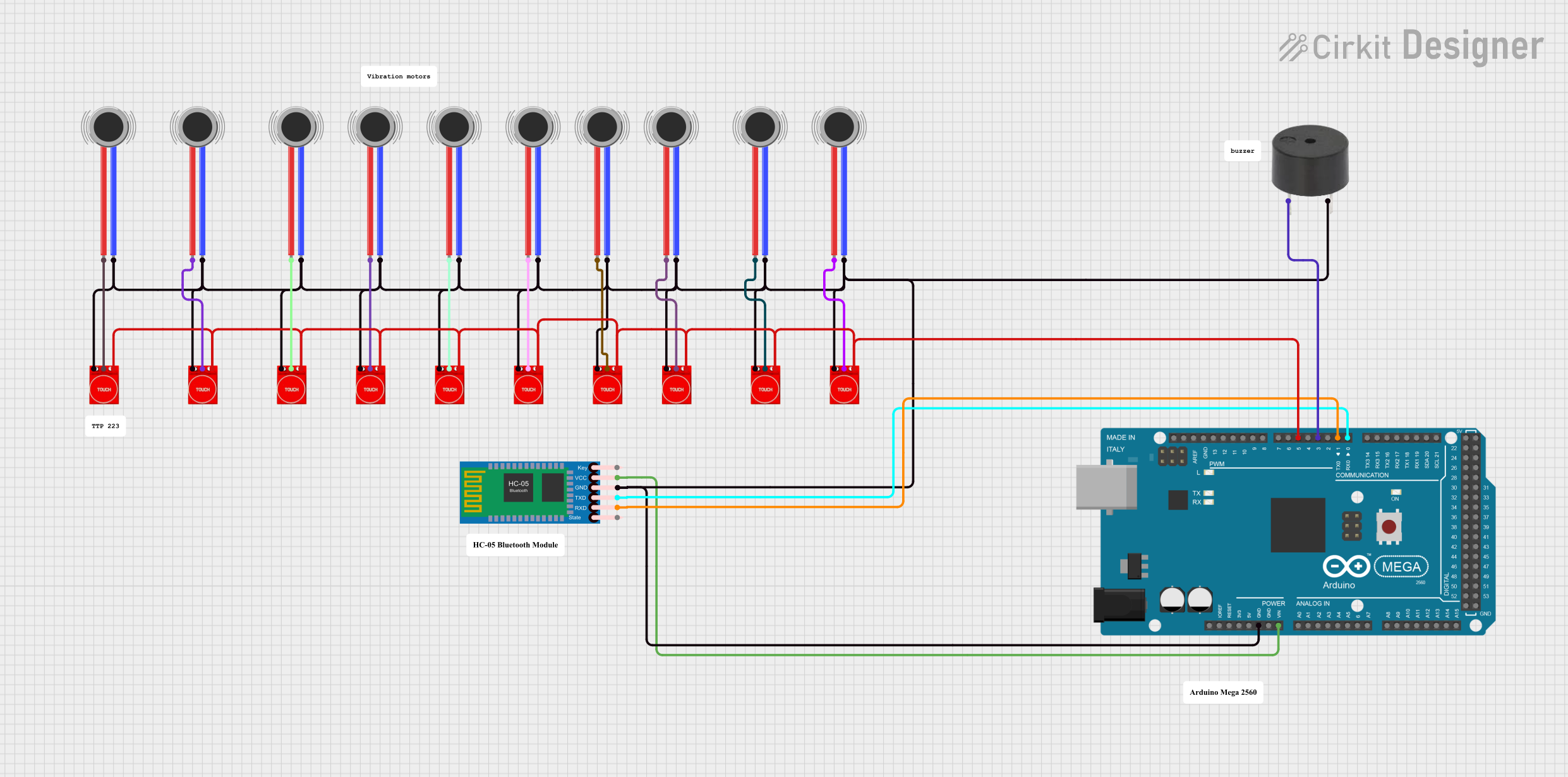
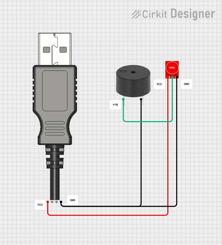
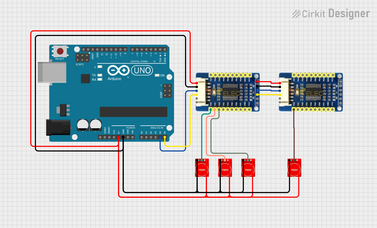

Explore Projects Built with Touch Sensor TTP233
Technical Specifications
Key Technical Details
- Operating Voltage: 2.0V to 5.5V
- Response Time: Max 220ms at VDD=3V
- Touch Pad Detection: Capacitive
- Output Type: Active Low (TTL compatible)
- Operating Current: 2.5uA (typical) at VDD=3V, no touch
- Interface: Digital Signal Output
Pin Configuration and Descriptions
| Pin Number | Name | Description |
|---|---|---|
| 1 | VDD | Power supply (2.0V to 5.5V) |
| 2 | GND | Ground connection |
| 3 | SIG | Digital signal output; active low |
| 4 | NC | Not connected (reserved for future use) |
Usage Instructions
Integration with a Circuit
To use the TTP233 touch sensor in a circuit, follow these steps:
- Connect the VDD pin to a power supply within the range of 2.0V to 5.5V.
- Connect the GND pin to the ground of your power supply.
- Connect the SIG pin to a digital input pin on your microcontroller, such as an Arduino UNO.
Important Considerations and Best Practices
- Ensure that the power supply voltage does not exceed the maximum rating of 5.5V to prevent damage to the sensor.
- Avoid placing the sensor in an environment with high humidity or the presence of conductive liquids, as these can trigger false touch detections.
- The touch pad area should be clean and free from any conductive materials that could interfere with the sensor's operation.
- For optimal performance, calibrate the sensor in the final installation environment to account for any parasitic capacitance.
Example Code for Arduino UNO
// Include the Arduino digital I/O library
#include <Arduino.h>

// Define the touch sensor pin
const int touchPin = 2; // Connect the SIG pin of the TTP233 to digital pin 2

void setup() {
  // Initialize the touchPin as an input
  pinMode(touchPin, INPUT);
  // Begin serial communication at 9600 baud rate
  Serial.begin(9600);
}

void loop() {
  // Read the state of the touch sensor
  int touchState = digitalRead(touchPin);

  // Check if the sensor is touched
  if (touchState == LOW) { // Remember the sensor output is active low
    // If touched, print a message to the serial monitor
    Serial.println("Touch detected!");
  } else {
    // If not touched, print a different message
    Serial.println("No touch detected.");
  }

  // Small delay to avoid overwhelming the serial monitor
  delay(100);
}
Troubleshooting and FAQs
Common Issues
- Sensor not responding to touch: Ensure that the sensor is properly powered and that the SIG pin is correctly connected to the microcontroller.
- False triggers or no detection: Check for any conductive debris or moisture on the touch pad. Also, ensure that the environment does not have excessive electrical noise.
Solutions and Tips for Troubleshooting
- Double-check all connections and ensure that the sensor is not damaged.
- If using a breadboard, ensure that all connections are secure and not loose.
- Test the sensor with a multimeter to ensure it is receiving the correct voltage.
- If the sensor is still not functioning correctly, try replacing it with a new one to rule out a defective unit.
FAQs
Q: Can the TTP233 sensor detect touch through materials?
A: Yes, the TTP233 can detect touch through thin, non-conductive materials like plastic or glass.
Q: Is it possible to adjust the sensitivity of the TTP233 sensor?
A: The sensitivity is not directly adjustable on the basic TTP233 module. However, some modules may have additional components or settings to adjust sensitivity.
Q: How long is the sensor's response time?
A: The maximum response time is approximately 220ms at a supply voltage of 3V.
Q: Can the TTP233 sensor work with a 3.3V logic level?
A: Yes, the TTP233 can operate at voltages as low as 2.0V, making it compatible with 3.3V logic levels.