How to Use Keyestudio poti: Examples, Pinouts, and Specs
Introduction
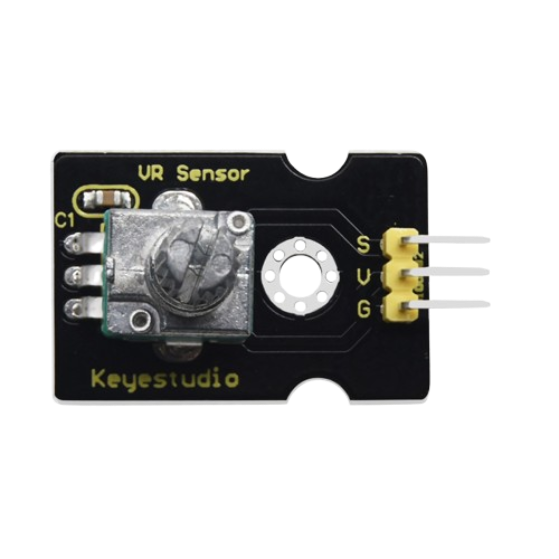
The Keyestudio Poti is a potentiometer module designed for adjusting resistance in electronic circuits. It allows users to variably control voltage or current, making it an essential component for applications requiring fine-tuning or calibration. This module is widely used in projects involving analog input adjustments, such as controlling brightness, motor speed, or audio volume.
Explore Projects Built with Keyestudio poti
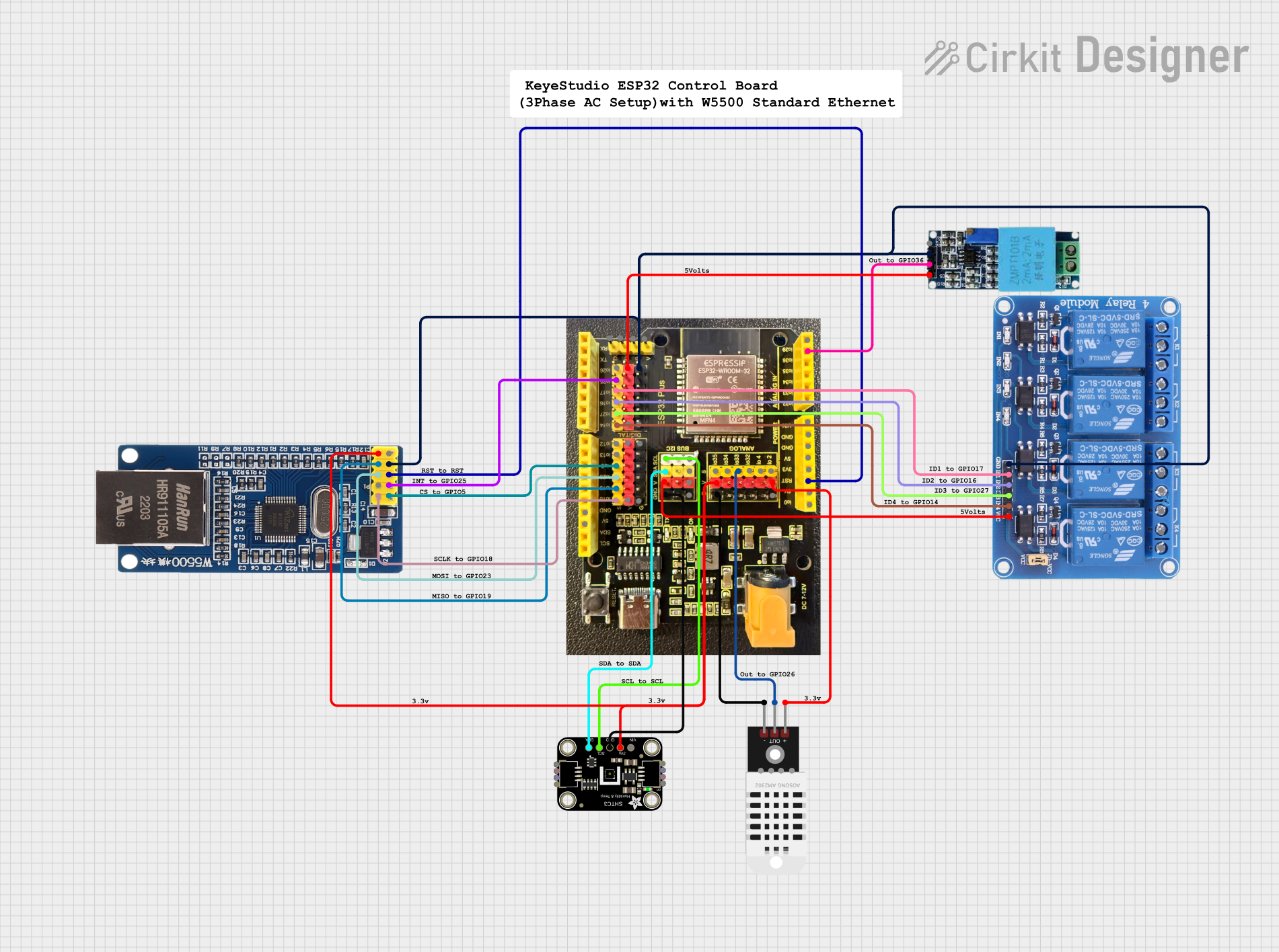
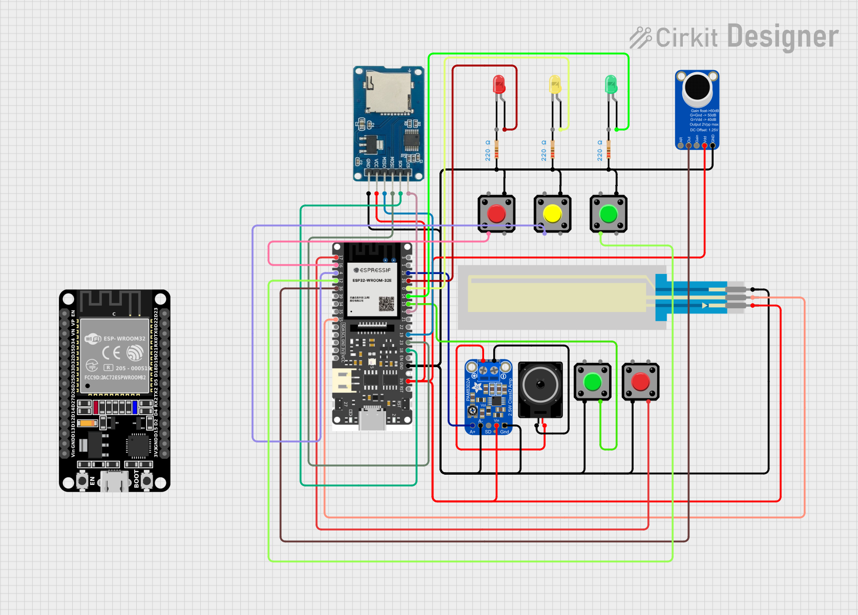
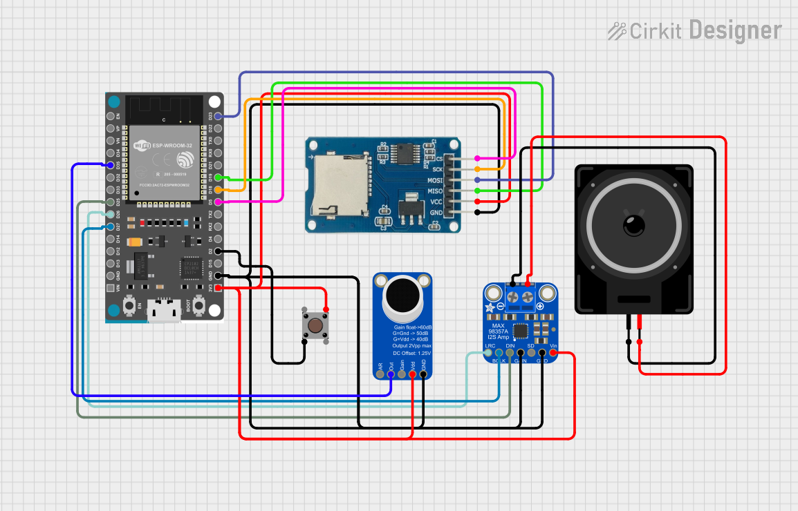

Explore Projects Built with Keyestudio poti
Common Applications and Use Cases
- Analog signal adjustment in microcontroller projects
- Brightness control for LEDs
- Motor speed regulation
- Audio volume control
- Calibration of sensor inputs
Technical Specifications
The Keyestudio Poti module is built for ease of use and compatibility with microcontroller platforms like Arduino. Below are its key technical details:
Key Specifications
| Parameter | Value |
|---|---|
| Manufacturer | Keyestudio |
| Part ID | Poti |
| Operating Voltage | 3.3V - 5V |
| Resistance Range | 10 kΩ |
| Output Type | Analog |
| Dimensions | 30mm x 20mm x 15mm |
| Connector Type | 3-pin header (GND, VCC, OUT) |
Pin Configuration and Descriptions
| Pin Name | Description |
|---|---|
| GND | Ground connection for the module |
| VCC | Power supply input (3.3V or 5V) |
| OUT | Analog output signal proportional to resistance |
Usage Instructions
How to Use the Keyestudio Poti in a Circuit
Connect the Module:
- Connect the
GNDpin to the ground of your power source or microcontroller. - Connect the
VCCpin to a 3.3V or 5V power supply. - Connect the
OUTpin to an analog input pin on your microcontroller or to the desired circuit.
- Connect the
Adjust the Potentiometer:
- Rotate the knob on the potentiometer to vary the resistance.
- The analog output voltage on the
OUTpin will change proportionally to the knob's position.
Read the Output:
- If connected to a microcontroller, read the analog signal from the
OUTpin using an ADC (Analog-to-Digital Converter) pin.
- If connected to a microcontroller, read the analog signal from the
Important Considerations and Best Practices
- Ensure the operating voltage does not exceed the specified range (3.3V - 5V).
- Avoid applying excessive force when turning the potentiometer knob to prevent damage.
- Use a pull-down resistor on the
OUTpin if the signal is unstable in your circuit. - For precise measurements, calibrate the potentiometer's output in your application.
Example: Using Keyestudio Poti with Arduino UNO
Below is an example of how to use the Keyestudio Poti module with an Arduino UNO to read the analog output and display the value in the Serial Monitor.
// Define the analog pin connected to the potentiometer's OUT pin
const int potentiometerPin = A0;

void setup() {
  // Initialize the Serial Monitor for debugging
  Serial.begin(9600);
}

void loop() {
  // Read the analog value from the potentiometer
  int potValue = analogRead(potentiometerPin);

  // Map the analog value (0-1023) to a voltage range (0-5V)
  float voltage = potValue * (5.0 / 1023.0);

  // Print the raw value and voltage to the Serial Monitor
  Serial.print("Analog Value: ");
  Serial.print(potValue);
  Serial.print(" | Voltage: ");
  Serial.print(voltage);
  Serial.println(" V");

  // Add a short delay for stability
  delay(500);
}
Notes:
- Connect the
OUTpin of the Keyestudio Poti to theA0pin on the Arduino UNO. - Ensure the
VCCandGNDpins are connected to the Arduino's5VandGNDpins, respectively.
Troubleshooting and FAQs
Common Issues and Solutions
No Output Signal:
- Cause: Incorrect wiring or loose connections.
- Solution: Double-check the connections to ensure
GND,VCC, andOUTare properly connected.
Unstable Output Signal:
- Cause: Electrical noise or lack of a pull-down resistor.
- Solution: Add a pull-down resistor (e.g., 10 kΩ) between the
OUTpin andGND.
Output Voltage Does Not Change:
- Cause: Faulty potentiometer or damaged module.
- Solution: Test the module with a multimeter to verify functionality. Replace if necessary.
Arduino Reads Incorrect Values:
- Cause: Incorrect analog pin configuration or power supply issues.
- Solution: Verify the analog pin assignment in the code and ensure the power supply is stable.
FAQs
Q1: Can I use the Keyestudio Poti with a 3.3V microcontroller like ESP32?
A1: Yes, the module is compatible with 3.3V systems. Ensure the VCC pin is connected to a 3.3V power source.
Q2: What is the maximum resistance of the potentiometer?
A2: The potentiometer has a maximum resistance of 10 kΩ.
Q3: Can I use this module to directly control high-power devices?
A3: No, the module is designed for low-power signal adjustments. Use it to control a driver circuit or microcontroller input for high-power applications.
Q4: How do I clean the potentiometer if it becomes noisy or unresponsive?
A4: Use a small amount of contact cleaner and rotate the knob several times to clean the internal contacts.
By following this documentation, you can effectively integrate the Keyestudio Poti module into your projects for precise analog control.