How to Use GPS模块: Examples, Pinouts, and Specs
Introduction
The GPS模块 by 大夏龙雀 is a high-performance GPS module designed to receive signals from GPS satellites and provide precise location data, including latitude, longitude, and altitude. This module is ideal for applications requiring accurate positioning, such as navigation systems, vehicle tracking, geofencing, and IoT devices.
With its compact design and reliable performance, the GPS模块 is suitable for both hobbyist projects and professional applications. It supports standard communication protocols, making it easy to integrate with microcontrollers like Arduino, Raspberry Pi, and other embedded systems.
Explore Projects Built with GPS模块

Explore Projects Built with GPS模块
Technical Specifications
Below are the key technical details of the GPS模块:
| Parameter | Specification |
|---|---|
| Manufacturer | 大夏龙雀 |
| Input Voltage | 3.3V to 5.0V |
| Operating Current | 20mA (typical) |
| Communication Protocol | UART (default), TTL |
| Baud Rate | 9600 bps (default, configurable) |
| Positioning Accuracy | ±2.5 meters (open sky) |
| Update Rate | 1Hz (default), configurable up to 10Hz |
| Operating Temperature | -40°C to +85°C |
| Dimensions | 25mm x 25mm x 6mm |
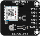
Pin Configuration
The GPS模块 has a simple pinout for easy integration. Below is the pin configuration:
| Pin | Name | Description |
|---|---|---|
| 1 | VCC | Power supply input (3.3V to 5.0V) |
| 2 | GND | Ground connection |
| 3 | TX | UART Transmit pin (sends GPS data) |
| 4 | RX | UART Receive pin (receives configuration commands) |
| 5 | PPS | Pulse Per Second output for precise timing (optional) |
Usage Instructions
How to Use the GPS模块 in a Circuit
- Power the Module: Connect the
VCCpin to a 3.3V or 5.0V power source and theGNDpin to ground. - Connect UART Pins:
- Connect the
TXpin of the GPS模块 to the RX pin of your microcontroller (e.g., Arduino). - Connect the
RXpin of the GPS模块 to the TX pin of your microcontroller.
- Connect the
- Antenna Placement: Ensure the GPS antenna has a clear view of the sky for optimal signal reception.
- Read GPS Data: Use a serial monitor or microcontroller code to read the NMEA sentences (standard GPS data format) transmitted by the module.
Important Considerations and Best Practices
- Power Supply: Ensure a stable power supply to avoid performance issues.
- Antenna Positioning: Place the antenna away from obstructions and sources of interference (e.g., metal objects, Wi-Fi routers).
- Baud Rate Configuration: If needed, configure the baud rate using appropriate commands to match your system requirements.
- Cold Start vs. Warm Start: The module may take longer to acquire a GPS fix during a cold start (first power-up) compared to a warm start (subsequent power-ups).
Example: Using GPS模块 with Arduino UNO
Below is an example code to interface the GPS模块 with an Arduino UNO and read GPS data:
#include <SoftwareSerial.h>

// Define GPS module pins connected to Arduino
#define RXPin 4  // GPS TX pin connected to Arduino pin 4
#define TXPin 3  // GPS RX pin connected to Arduino pin 3

// Set up a SoftwareSerial instance for communication with the GPS module
SoftwareSerial gpsSerial(RXPin, TXPin);

void setup() {
  Serial.begin(9600);        // Initialize Serial Monitor at 9600 baud
  gpsSerial.begin(9600);     // Initialize GPS module communication at 9600 baud
  Serial.println("GPS模块 initialized. Waiting for data...");
}

void loop() {
  // Check if data is available from the GPS module
  while (gpsSerial.available()) {
    char c = gpsSerial.read();  // Read a character from the GPS module
    Serial.print(c);            // Print the character to the Serial Monitor
  }
}
Notes:
- Ensure the
RXPinandTXPinin the code match your wiring. - Use a Serial Monitor (e.g., in the Arduino IDE) to view the GPS data output.
Troubleshooting and FAQs
Common Issues and Solutions
No GPS Fix (No Location Data)
- Cause: Poor antenna placement or interference.
- Solution: Move the antenna to an open area with a clear view of the sky.
No Data Output
- Cause: Incorrect wiring or baud rate mismatch.
- Solution: Double-check the connections and ensure the baud rate is set to 9600 bps.
Unstable Data
- Cause: Insufficient power supply or interference.
- Solution: Use a stable power source and minimize nearby electronic interference.
PPS Pin Not Working
- Cause: PPS functionality not enabled.
- Solution: Refer to the module's advanced configuration commands to enable PPS.
FAQs
Q: Can the GPS模块 work indoors?
- A: The module may work indoors near windows, but performance is significantly better outdoors.
Q: How do I change the baud rate?
- A: Use specific configuration commands sent via the UART interface. Refer to the module's command set documentation.
Q: What is the default update rate?
- A: The default update rate is 1Hz, but it can be configured up to 10Hz for faster updates.
By following this documentation, you can effectively integrate and use the GPS模块 in your projects.