How to Use arducam ov2640 mini : Examples, Pinouts, and Specs
Introduction
The Arducam OV2640 Mini is a compact camera module equipped with a 2MP (megapixel) image sensor. It is designed for embedded systems and IoT (Internet of Things) applications, offering high-quality image and video capture in a small form factor. The module supports multiple resolutions, from low to high, and comes with a built-in lens, making it ideal for projects where space is limited.
Explore Projects Built with arducam ov2640 mini


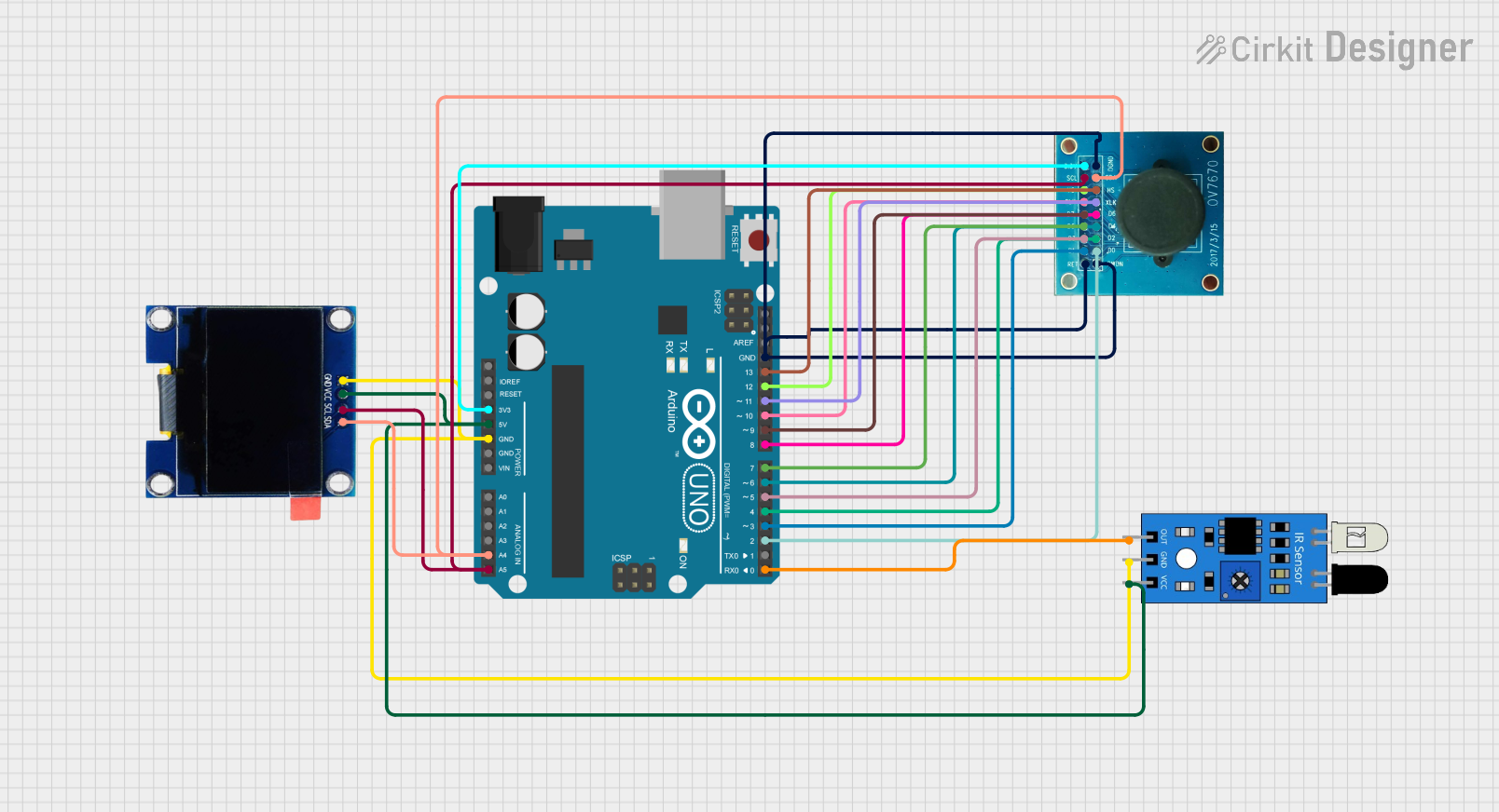
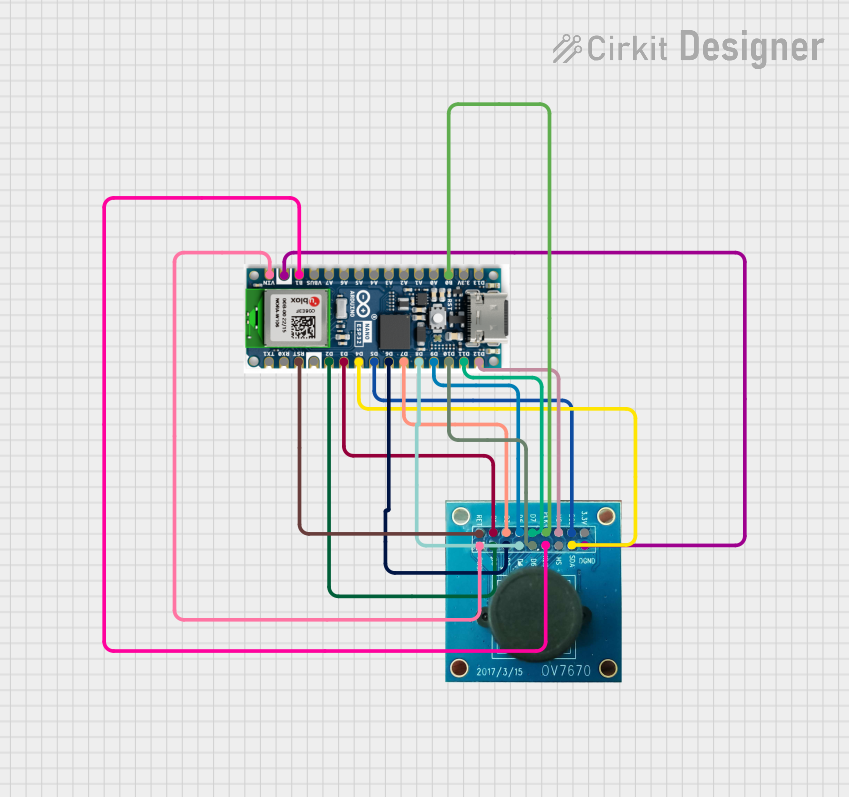
Explore Projects Built with arducam ov2640 mini
Common Applications and Use Cases
- Home automation and security systems
- IoT devices with image or video capture capabilities
- Robotics and machine vision
- DIY projects requiring compact camera modules
- Wildlife monitoring and surveillance systems
Technical Specifications
Key Technical Details
- Image Sensor: OV2640, 2MP CMOS sensor
- Resolution: Up to 1600x1200 (UXGA)
- Lens: Built-in fixed-focus lens
- Interface: SPI (Serial Peripheral Interface)
- Power Supply Voltage: 3.3V
- Current Consumption: ~100mA (active mode)
- Operating Temperature: -20°C to 70°C
- Dimensions: 25mm x 24mm
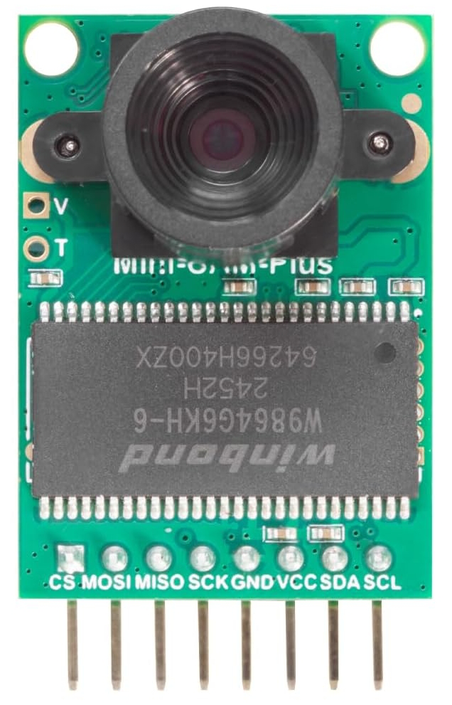
Pin Configuration and Descriptions
The Arducam OV2640 Mini has a 7-pin interface for communication and power. Below is the pinout:
| Pin | Name | Description |
|---|---|---|
| 1 | GND | Ground connection |
| 2 | VCC | Power supply (3.3V) |
| 3 | SCL | SPI clock signal |
| 4 | SDA | SPI data signal |
| 5 | CS | Chip select (active low) |
| 6 | MISO | Master In Slave Out (data from camera to microcontroller) |
| 7 | RESET | Reset pin (active low, used to reset the camera module) |
Usage Instructions
How to Use the Component in a Circuit
- Power Supply: Connect the VCC pin to a 3.3V power source and the GND pin to ground.
- SPI Communication: Connect the SCL, SDA, CS, and MISO pins to the corresponding SPI pins on your microcontroller.
- Reset: Optionally, connect the RESET pin to a GPIO pin on your microcontroller for software-controlled resets.
- Lens Adjustment: The built-in lens is fixed-focus, so no manual adjustment is required.
Important Considerations and Best Practices
- Ensure the power supply is stable and within the specified voltage range (3.3V).
- Use short and properly shielded wires for SPI connections to minimize noise.
- Avoid exposing the module to extreme temperatures or humidity.
- If using with an Arduino UNO, note that the SPI pins are shared with other peripherals, so plan your connections accordingly.
Example Code for Arduino UNO
Below is an example of how to interface the Arducam OV2640 Mini with an Arduino UNO to capture an image:
#include <ArduCAM.h>
#include <Wire.h>
#include <SPI.h>

// Define the camera module type
#define OV2640_MINI_2MP
ArduCAM myCAM(OV2640, 10); // CS pin is connected to pin 10 on Arduino

void setup() {
  Serial.begin(115200);
  Wire.begin();
  SPI.begin();

  // Initialize the camera module
  pinMode(10, OUTPUT);
  digitalWrite(10, HIGH);
  myCAM.initCAM();

  // Test camera connection
  if (myCAM.checkCameraModule() == 0) {
    Serial.println("Camera module detected.");
  } else {
    Serial.println("Camera module not detected. Check connections.");
    while (1);
  }

  // Set image resolution
  myCAM.setImageSize(OV2640_1600x1200); // Set to UXGA resolution
  Serial.println("Camera initialized and ready.");
}

void loop() {
  // Capture an image
  myCAM.startCapture();
  while (!myCAM.checkCaptureComplete()) {
    delay(10); // Wait for capture to complete
  }
  Serial.println("Image captured!");

  // Read image data (example: send to serial or save to SD card)
  uint8_t buffer[256];
  uint32_t length = myCAM.readImageLength();
  Serial.print("Image size: ");
  Serial.println(length);

  while (length > 0) {
    uint16_t bytesToRead = min(length, sizeof(buffer));
    myCAM.readImageData(buffer, bytesToRead);
    Serial.write(buffer, bytesToRead); // Send image data over serial
    length -= bytesToRead;
  }

  Serial.println("Image transfer complete.");
  delay(5000); // Wait before capturing the next image
}
Notes:
- Install the ArduCAM library in the Arduino IDE before running the code.
- Connect the CS pin of the camera module to pin 10 on the Arduino UNO.
- The image data can be sent to an SD card or processed further as needed.
Troubleshooting and FAQs
Common Issues and Solutions
Camera Not Detected
- Cause: Incorrect wiring or loose connections.
- Solution: Double-check all connections, especially the CS, SCL, and SDA pins.
Image Capture Fails
- Cause: Insufficient power supply or incorrect SPI configuration.
- Solution: Ensure the power supply is stable and verify SPI settings in the code.
Poor Image Quality
- Cause: Dust on the lens or incorrect resolution settings.
- Solution: Clean the lens gently and verify the resolution settings in the code.
Arduino Freezes During Operation
- Cause: Insufficient memory on the Arduino UNO.
- Solution: Use a microcontroller with more memory, such as the Arduino Mega, or reduce the image resolution.
FAQs
Can I use the Arducam OV2640 Mini with a Raspberry Pi?
- Yes, the module can be used with a Raspberry Pi, but you will need to use the SPI interface and appropriate libraries.
What is the maximum frame rate of the OV2640?
- The OV2640 supports up to 15 fps at UXGA resolution and higher frame rates at lower resolutions.
Can I adjust the focus of the lens?
- No, the lens is fixed-focus and cannot be adjusted manually.
Is the module compatible with 5V systems?
- No, the module operates at 3.3V. Use a level shifter if interfacing with a 5V system.
By following this documentation, you can successfully integrate the Arducam OV2640 Mini into your projects and troubleshoot common issues effectively.