
How to Use ATmega328 TQFP-32 on DIP Adapter: Examples, Pinouts, and Specs
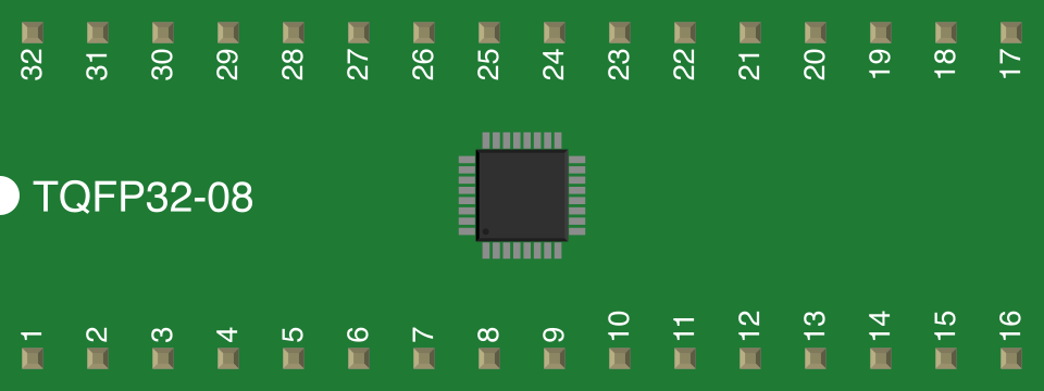
 Design with ATmega328 TQFP-32 on DIP Adapter in Cirkit Designer
Introduction
The ATmega328 TQFP-32 on DIP Adapter is a circuit board adapter designed to bridge the gap between the TQFP-32 package of the ATmega328 microcontroller and the more prototyping-friendly DIP (Dual In-line Package) format. This adapter allows users to easily integrate the ATmega328 microcontroller into breadboards or other DIP-compatible sockets, simplifying prototyping and development.
Explore Projects Built with ATmega328 TQFP-32 on DIP Adapter
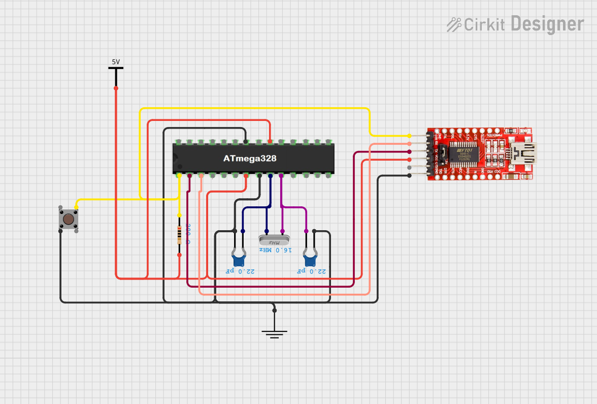 Open Project in Cirkit Designer
 Open Project in Cirkit Designer
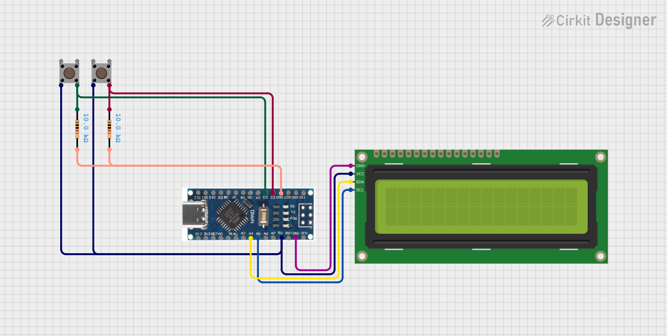 Open Project in Cirkit Designer
 Open Project in Cirkit Designer
Explore Projects Built with ATmega328 TQFP-32 on DIP Adapter
Open Project in Cirkit DesignerOpen Project in Cirkit DesignerOpen Project in Cirkit DesignerOpen Project in Cirkit DesignerCommon Applications and Use Cases
- Prototyping with the ATmega328 microcontroller on breadboards
- Developing and testing Arduino-compatible projects
- Educational purposes for learning microcontroller programming
- Replacing DIP-packaged ATmega328 chips in existing designs
Technical Specifications
Key Technical Details
- Microcontroller Compatibility: ATmega328 in TQFP-32 package
- Adapter Dimensions: Standard DIP-28 footprint
- Pin Pitch: 2.54 mm (DIP side), 0.8 mm (TQFP side)
- Voltage Range: Compatible with ATmega328 operating voltage (1.8V–5.5V)
- Material: FR4 PCB with gold-plated pads for durability
- Mounting: Pre-soldered TQFP-32 socket with DIP pins
Pin Configuration and Descriptions
The adapter maps the TQFP-32 pins of the ATmega328 microcontroller to a standard DIP-28 layout. Below is the pin mapping:
| DIP Pin | TQFP Pin | Function | Description |
|---|---|---|---|
| 1 | 4 | PC6/RESET | Reset pin |
| 2 | 5 | PD0/RXD | UART Receive (RX) |
| 3 | 6 | PD1/TXD | UART Transmit (TX) |
| 4 | 7 | PD2/INT0 | External Interrupt 0 |
| 5 | 8 | PD3/INT1/OC2B | External Interrupt 1 / Timer2 Output B |
| 6 | 9 | PD4/OC0B | Timer0 Output B |
| 7 | 10 | VCC | Power Supply |
| 8 | 11 | GND | Ground |
| 9 | 12 | PB6/XTAL1 | Crystal Oscillator Input |
| 10 | 13 | PB7/XTAL2 | Crystal Oscillator Output |
| 11 | 14 | PD5/OC0A/T1 | Timer0 Output A / Timer1 Input |
| 12 | 15 | PD6/OC0A/AIN0 | Timer0 Output A / Analog Comparator In 0 |
| 13 | 16 | PD7/AIN1 | Analog Comparator In 1 |
| 14 | 17 | PB0/ICP1/OC1A | Timer1 Input Capture / Output Compare A |
| 15 | 18 | PB1/OC1A/OC1B | Timer1 Output Compare A / Output Compare B |
| 16 | 19 | PB2/SS/OC1B | SPI Slave Select / Timer1 Output Compare B |
| 17 | 20 | PB3/MOSI/OC2A | SPI Master Out Slave In / Timer2 Output A |
| 18 | 21 | PB4/MISO | SPI Master In Slave Out |
| 19 | 22 | PB5/SCK | SPI Clock |
| 20 | 23 | AVCC | Analog Power Supply |
| 21 | 24 | ADC6 | Analog Input Channel 6 |
| 22 | 25 | ADC7 | Analog Input Channel 7 |
| 23 | 26 | PC0/ADC0 | Analog Input Channel 0 |
| 24 | 27 | PC1/ADC1 | Analog Input Channel 1 |
| 25 | 28 | PC2/ADC2 | Analog Input Channel 2 |
| 26 | 29 | PC3/ADC3 | Analog Input Channel 3 |
| 27 | 30 | PC4/ADC4/SDA | Analog Input Channel 4 / I2C Data Line |
| 28 | 31 | PC5/ADC5/SCL | Analog Input Channel 5 / I2C Clock Line |
Usage Instructions
How to Use the Adapter in a Circuit
- Insert the Adapter into a Breadboard: Place the DIP pins of the adapter into the breadboard. Ensure the pins are aligned with the breadboard rows.
- Connect Power and Ground: Supply the appropriate voltage (e.g., 5V) to the VCC pin and connect the GND pin to the ground rail.
- Connect Peripherals: Use jumper wires to connect the microcontroller pins to external components such as LEDs, sensors, or communication modules.
- Program the Microcontroller: Use an ISP (In-System Programmer) or an Arduino UNO as a programmer to upload code to the ATmega328 microcontroller.
Important Considerations and Best Practices
- Power Supply: Ensure the voltage supplied to the VCC pin matches the operating voltage of the ATmega328 (typically 5V or 3.3V).
- Crystal Oscillator: If using an external crystal oscillator, connect it to the XTAL1 and XTAL2 pins, and add the appropriate capacitors.
- Bypass Capacitors: Place a 0.1 µF capacitor between VCC and GND near the microcontroller to stabilize the power supply.
- Programming: Use the RESET pin to enable programming mode. Ensure the programmer is compatible with the ATmega328.
Example Code for Arduino UNO
The following example demonstrates how to blink an LED connected to pin PB5 (DIP pin 19):
// Blink an LED connected to PB5 (DIP pin 19)

// Define the pin number for the LED
const int ledPin = 13; // PB5 corresponds to Arduino pin 13

void setup() {
  pinMode(ledPin, OUTPUT); // Set the LED pin as an output
}

void loop() {
  digitalWrite(ledPin, HIGH); // Turn the LED on
  delay(1000);                // Wait for 1 second
  digitalWrite(ledPin, LOW);  // Turn the LED off
  delay(1000);                // Wait for 1 second
}
Troubleshooting and FAQs
Common Issues and Solutions
Microcontroller Not Responding:
- Cause: Incorrect power supply or loose connections.
- Solution: Verify that the VCC and GND pins are properly connected and the voltage is within the operating range.
Unable to Program the Microcontroller:
- Cause: Incorrect programmer settings or missing connections.
- Solution: Ensure the RESET pin is connected to the programmer and the correct microcontroller is selected in the programming software.
Peripheral Devices Not Working:
- Cause: Incorrect pin connections or missing pull-up resistors.
- Solution: Double-check the wiring and add pull-up resistors for I2C or other communication protocols if needed.
Overheating:
- Cause: Excessive current draw or short circuits.
- Solution: Check for short circuits and ensure the connected peripherals do not exceed the current limits of the microcontroller.
FAQs
Can I use this adapter with other TQFP-32 microcontrollers?
- No, this adapter is specifically designed for the ATmega328 microcontroller.
Do I need an external crystal oscillator?
- The ATmega328 has an internal oscillator, but for precise timing, an external crystal oscillator is recommended.
Can I use this adapter with an Arduino UNO?
- Yes, the ATmega328 on this adapter can be programmed using an Arduino UNO as an ISP programmer.
What is the maximum current the adapter can handle?
- The current is limited by the ATmega328 microcontroller, which can source/sink up to 40 mA per pin (recommended maximum is 20 mA).