Cirkit Designer Logo
Cirkit Designer
Your all-in-one circuit design IDE
Home / 
Component Documentation

How to Use relay tomzn toct 1-25: Examples, Pinouts, and Specs

Image of relay tomzn toct 1-25
Cirkit Designer LogoDesign with relay tomzn toct 1-25 in Cirkit Designer

Introduction

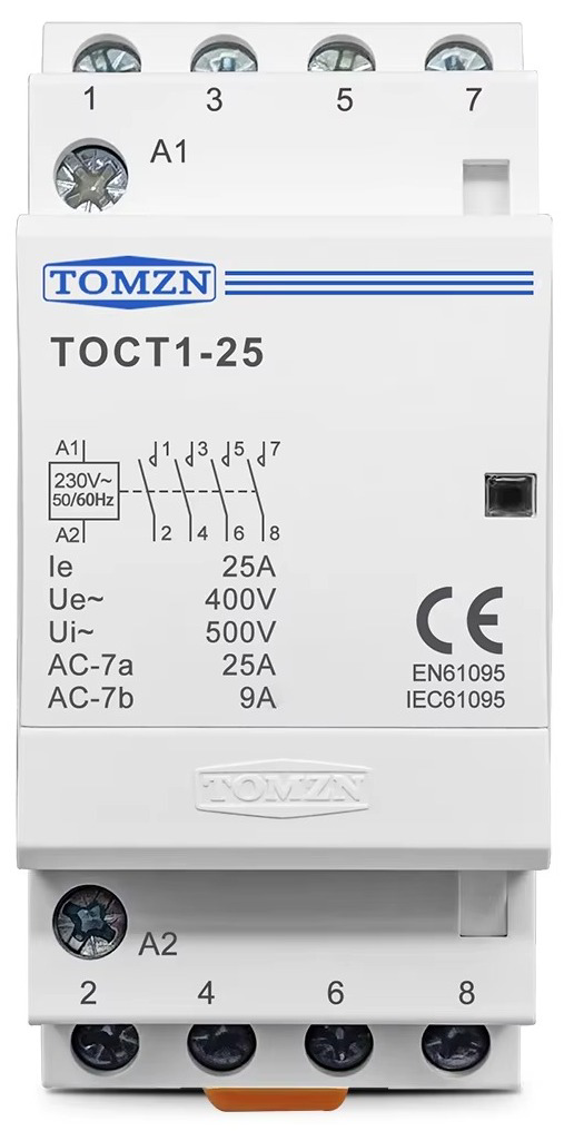
The TOMZN TOCT 1-25 is an electromechanical relay designed for switching applications. It operates by using an electromagnetic coil to open or close its internal contacts, enabling control of high-power circuits with low-power signals. This relay is versatile and suitable for a wide range of voltage and current ratings, making it ideal for industrial automation, home appliances, and other electrical control systems.

Explore Projects Built with relay tomzn toct 1-25

Use Cirkit Designer to design, explore, and prototype these projects online. Some projects support real-time simulation. Click "Open Project" to start designing instantly!
Sequential Timer-Controlled Relay Switching Circuit
Image of Mark Murry Fantasy Lights: A project utilizing relay tomzn toct 1-25 in a practical application
This circuit is a sequential relay timer utilizing three 555 timers configured as astable multivibrators to generate timing pulses. These pulses clock a 4017 decade counter, which sequentially activates multiple relay modules. Timing adjustments are possible through potentiometers and fixed resistors, while capacitors set the oscillation frequency.
Cirkit Designer LogoOpen Project in Cirkit Designer
Arduino-Based Wireless Power Transmission System with Copper Coils
Image of nagesh: A project utilizing relay tomzn toct 1-25 in a practical application
This circuit consists of multiple copper coils connected to transmitters and a receiver, likely forming a wireless power transfer or communication system. The transmitters are connected to individual coils, and the receiver is connected to another coil, facilitating the transmission and reception of signals or power wirelessly.
Cirkit Designer LogoOpen Project in Cirkit Designer
Sound and Motion-Activated Switching Circuit with 4017 Decade Counter and BC547 Transistors
Image of m.s: A project utilizing relay tomzn toct 1-25 in a practical application
This circuit is a sequential control system with a 4017 decade counter at its core, driving relays through transistors based on its output states. It includes toggle switches and a PIR sensor for triggering events, a condenser microphone for sound detection, and an LED for visual indication. The circuit operates without a microcontroller, relying on the counter's sequence and external inputs to control the connected loads.
Cirkit Designer LogoOpen Project in Cirkit Designer
Cellular-Enabled IoT Device with Real-Time Clock and Power Management
Image of LRCM PHASE 2 BASIC: A project utilizing relay tomzn toct 1-25 in a practical application
This circuit features a LilyGo-SIM7000G module for cellular communication and GPS functionality, interfaced with an RTC DS3231 for real-time clock capabilities. It includes voltage sensing through two voltage sensor modules, and uses an 8-channel opto-coupler for isolating different parts of the circuit. Power management is handled by a buck converter connected to a DC power source and batteries, with a fuse for protection and a rocker switch for on/off control. Additionally, there's an LED for indication purposes.
Cirkit Designer LogoOpen Project in Cirkit Designer

Explore Projects Built with relay tomzn toct 1-25

Use Cirkit Designer to design, explore, and prototype these projects online. Some projects support real-time simulation. Click "Open Project" to start designing instantly!
Image of Mark Murry Fantasy Lights: A project utilizing relay tomzn toct 1-25 in a practical application
Sequential Timer-Controlled Relay Switching Circuit
This circuit is a sequential relay timer utilizing three 555 timers configured as astable multivibrators to generate timing pulses. These pulses clock a 4017 decade counter, which sequentially activates multiple relay modules. Timing adjustments are possible through potentiometers and fixed resistors, while capacitors set the oscillation frequency.
Cirkit Designer LogoOpen Project in Cirkit Designer
Image of nagesh: A project utilizing relay tomzn toct 1-25 in a practical application
Arduino-Based Wireless Power Transmission System with Copper Coils
This circuit consists of multiple copper coils connected to transmitters and a receiver, likely forming a wireless power transfer or communication system. The transmitters are connected to individual coils, and the receiver is connected to another coil, facilitating the transmission and reception of signals or power wirelessly.
Cirkit Designer LogoOpen Project in Cirkit Designer
Image of m.s: A project utilizing relay tomzn toct 1-25 in a practical application
Sound and Motion-Activated Switching Circuit with 4017 Decade Counter and BC547 Transistors
This circuit is a sequential control system with a 4017 decade counter at its core, driving relays through transistors based on its output states. It includes toggle switches and a PIR sensor for triggering events, a condenser microphone for sound detection, and an LED for visual indication. The circuit operates without a microcontroller, relying on the counter's sequence and external inputs to control the connected loads.
Cirkit Designer LogoOpen Project in Cirkit Designer
Image of LRCM PHASE 2 BASIC: A project utilizing relay tomzn toct 1-25 in a practical application
Cellular-Enabled IoT Device with Real-Time Clock and Power Management
This circuit features a LilyGo-SIM7000G module for cellular communication and GPS functionality, interfaced with an RTC DS3231 for real-time clock capabilities. It includes voltage sensing through two voltage sensor modules, and uses an 8-channel opto-coupler for isolating different parts of the circuit. Power management is handled by a buck converter connected to a DC power source and batteries, with a fuse for protection and a rocker switch for on/off control. Additionally, there's an LED for indication purposes.
Cirkit Designer LogoOpen Project in Cirkit Designer

Common Applications and Use Cases

  • Industrial automation systems
  • Home electrical appliances
  • Motor control circuits
  • Lighting systems
  • Power distribution and protection circuits

Technical Specifications

The TOMZN TOCT 1-25 relay is designed to handle moderate to high power loads with reliable performance. Below are its key technical details:

General Specifications

Parameter Value
Rated Voltage (Coil) 12V DC / 24V DC / 230V AC
Rated Current (Contacts) Up to 25A
Contact Configuration SPST (Single Pole Single Throw)
Operating Temperature -40°C to +70°C
Insulation Resistance ≥ 100MΩ
Dielectric Strength 2500V AC (coil to contacts)
Mounting Type DIN Rail

Pin Configuration and Descriptions

The relay typically features a set of terminals for both the coil and the load. Below is the pin configuration:

Pin Number Description
1 Coil Terminal (Positive)
2 Coil Terminal (Negative)
3 Common Contact (COM)
4 Normally Open Contact (NO)

Usage Instructions

How to Use the Relay in a Circuit

  1. Power the Coil: Connect the coil terminals (pins 1 and 2) to the appropriate voltage source (e.g., 12V DC, 24V DC, or 230V AC, depending on the relay model). Ensure the voltage matches the relay's rated coil voltage.
  2. Connect the Load: Wire the load circuit to the common (COM) and normally open (NO) terminals (pins 3 and 4). When the coil is energized, the NO contact will close, completing the circuit.
  3. Control the Coil: Use a low-power control signal (e.g., from a microcontroller or switch) to energize the coil and activate the relay.

Important Considerations and Best Practices

  • Voltage Matching: Always ensure the coil voltage matches the relay's rated voltage to avoid damage.
  • Current Rating: Do not exceed the relay's maximum current rating (25A) to prevent overheating or failure.
  • Flyback Diode: When using a DC coil, add a flyback diode across the coil terminals to protect the control circuit from voltage spikes.
  • Secure Mounting: Use a DIN rail for secure and stable mounting in industrial or home setups.
  • Isolation: Ensure proper electrical isolation between the control and load circuits to prevent interference or damage.

Example: Using the Relay with an Arduino UNO

Below is an example of how to control the TOMZN TOCT 1-25 relay using an Arduino UNO:

// Define the pin connected to the relay's coil
const int relayPin = 7;

void setup() {
  // Set the relay pin as an output
  pinMode(relayPin, OUTPUT);
  
  // Ensure the relay is off at startup
  digitalWrite(relayPin, LOW);
}

void loop() {
  // Turn the relay on
  digitalWrite(relayPin, HIGH);
  delay(5000); // Keep the relay on for 5 seconds
  
  // Turn the relay off
  digitalWrite(relayPin, LOW);
  delay(5000); // Keep the relay off for 5 seconds
}

Note: Use a transistor or relay driver module to interface the Arduino with the relay, as the Arduino's GPIO pins cannot directly supply the required current for the relay coil.

Troubleshooting and FAQs

Common Issues and Solutions

  1. Relay Not Activating:

    • Cause: Incorrect coil voltage or insufficient current.
    • Solution: Verify the coil voltage and ensure the power supply can provide adequate current.
  2. Contacts Not Switching:

    • Cause: Faulty wiring or damaged contacts.
    • Solution: Check the wiring and inspect the relay for physical damage.
  3. Excessive Heating:

    • Cause: Overloading the relay beyond its rated current.
    • Solution: Ensure the load current does not exceed 25A. Use a relay with a higher current rating if necessary.
  4. Noise or Chattering:

    • Cause: Unstable control signal or insufficient coil voltage.
    • Solution: Stabilize the control signal and verify the power supply voltage.

FAQs

Q1: Can I use the relay with an AC load?
Yes, the TOMZN TOCT 1-25 relay can switch both AC and DC loads, provided the load voltage and current are within the relay's rated specifications.

Q2: Do I need a heatsink for the relay?
No, a heatsink is not required for this relay. However, ensure proper ventilation to prevent overheating during prolonged use.

Q3: Can I use this relay for motor control?
Yes, the relay is suitable for motor control applications, but ensure the motor's starting current does not exceed the relay's maximum current rating.

Q4: How do I know if the relay is working?
You can hear a clicking sound when the relay switches. Additionally, you can measure continuity between the COM and NO terminals to confirm operation.