How to Use RockerSwitch4Pin: Examples, Pinouts, and Specs
Introduction
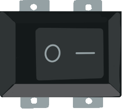
A Rocker Switch is a type of on/off switch that toggles between two positions, functioning as a binary device in electrical circuits. The 4-Pin Rocker Switch is a common variant that features two sets of terminals, which allows it to control a single device or circuit. It is widely used in household appliances, automotive applications, industrial machinery, and electronic devices due to its ease of operation and reliability.
Explore Projects Built with RockerSwitch4Pin


Explore Projects Built with RockerSwitch4Pin
Common Applications and Use Cases
- Power supply switches for electronic devices
- Automotive dashboards
- Control panels for machinery
- Lighting control switches
Technical Specifications
Key Technical Details
- Voltage Rating: Typically ranges from 110V to 250V
- Current Rating: Commonly rated for 10A to 20A at 120V or 240V AC
- Contact Configuration: SPST (Single Pole Single Throw) or DPDT (Double Pole Double Throw)
- Operating Temperature: -20°C to +85°C
- Electrical Life: 10,000 to 100,000 cycles
- Mechanical Life: 50,000 to 100,000 cycles
Pin Configuration and Descriptions
| Pin Number | Description | Notes |
|---|---|---|
| 1 | Input/Output Terminal 1 | Connect to power supply or load |
| 2 | Input/Output Terminal 1 | Connect to power supply or load |
| 3 | Switch Contact Terminal 1 | Connect to load or power supply |
| 4 | Switch Contact Terminal 2 | Connect to load or power supply |
Note: Pins 1 and 2 are electrically connected when the switch is in the "on" position, as are pins 3 and 4.
Usage Instructions
How to Use the Component in a Circuit
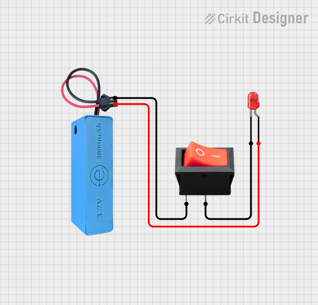
- Power Connection: Connect the power supply to pins 1 and 2. These pins are typically the input terminals.
- Load Connection: Connect the device or load that you want to control with the switch to pins 3 and 4.
- Mounting: Secure the switch in place, ensuring it is firmly attached to the panel or board to prevent movement during operation.
Important Considerations and Best Practices
- Voltage and Current Ratings: Always verify that the switch's ratings are compatible with the circuit's requirements.
- Wiring: Ensure that all connections are secure and that there is no risk of short circuits.
- Switch Orientation: Be mindful of the switch orientation to ensure the "on" and "off" positions are as desired.
- Testing: Test the switch in your circuit before finalizing the installation to ensure proper functionality.
Troubleshooting and FAQs
Common Issues Users Might Face
- Switch Does Not Operate: Check if the switch is properly mounted and that the terminals are not loose.
- Intermittent Operation: Inspect for any signs of damage or wear and ensure that the connections are secure.
- Overheating: Ensure that the current and voltage do not exceed the switch's ratings.
Solutions and Tips for Troubleshooting
- Secure Connections: Tighten any loose terminals and ensure wires are properly connected.
- Replace if Necessary: If the switch is damaged or has reached the end of its mechanical life, replace it with a new one.
- Check Ratings: Always use a switch with appropriate ratings for your application to prevent overheating and potential failure.
FAQs
Q: Can I use the Rocker Switch with a DC circuit? A: Yes, but ensure that the DC voltage and current do not exceed the switch's AC ratings.
Q: How do I know if the switch is in the "on" position? A: Typically, the side of the switch that is pressed down indicates the "on" position, but this can vary with design.
Q: Is it possible to control two separate circuits with a 4-pin Rocker Switch? A: No, a 4-pin Rocker Switch is designed to control one circuit. For controlling two circuits, a switch with more pins and a different configuration would be required.
Example Code for Arduino UNO
The following is an example of how to use a 4-Pin Rocker Switch with an Arduino UNO to control an LED.
// Define the pin connected to the Rocker Switch
const int rockerSwitchPin = 2;
// Define the pin connected to the LED
const int ledPin = 13;

void setup() {
  // Set the LED pin as an output
  pinMode(ledPin, OUTPUT);
  // Set the Rocker Switch pin as an input
  pinMode(rockerSwitchPin, INPUT);
}

void loop() {
  // Read the state of the Rocker Switch
  int switchState = digitalRead(rockerSwitchPin);

  // If the switch is in the "on" position, turn on the LED
  if (switchState == HIGH) {
    digitalWrite(ledPin, HIGH);
  } else {
    // If the switch is in the "off" position, turn off the LED
    digitalWrite(ledPin, LOW);
  }
}
Note: In this example, the Rocker Switch is assumed to be connected to the Arduino such that it closes the circuit between the rockerSwitchPin and ground when in the "on" position.