How to Use AMS1117 5.0 V: Examples, Pinouts, and Specs
Introduction
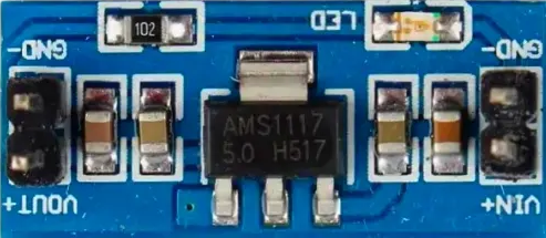
The AMS1117 5.0 V is a low dropout (LDO) voltage regulator designed to provide a stable 5.0 V output with a maximum output current of 1 A. It is widely used in power supply circuits to regulate voltage levels for microcontrollers, sensors, and other electronic devices. Its compact size and ease of use make it a popular choice for both hobbyists and professionals.
Explore Projects Built with AMS1117 5.0 V
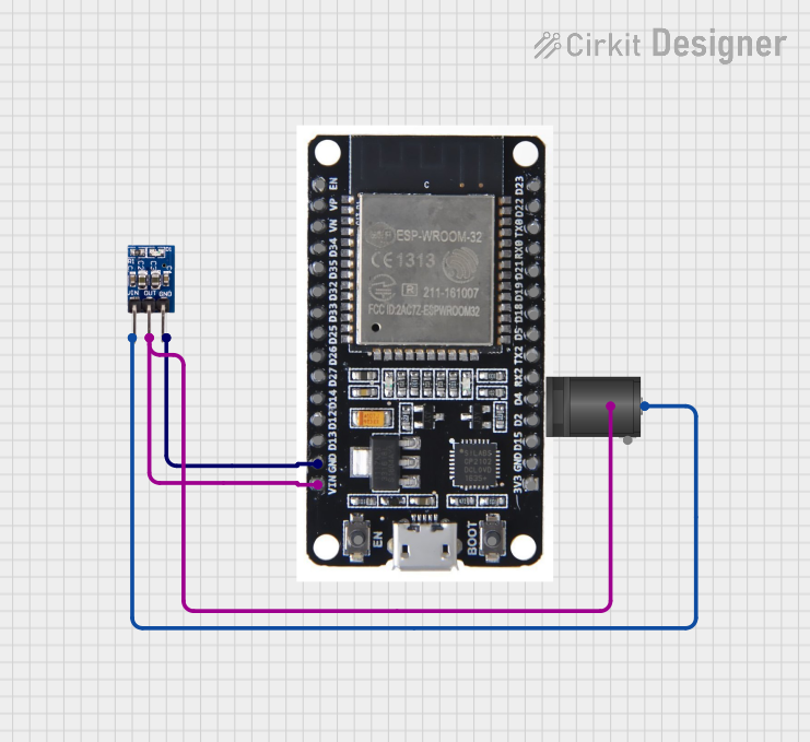

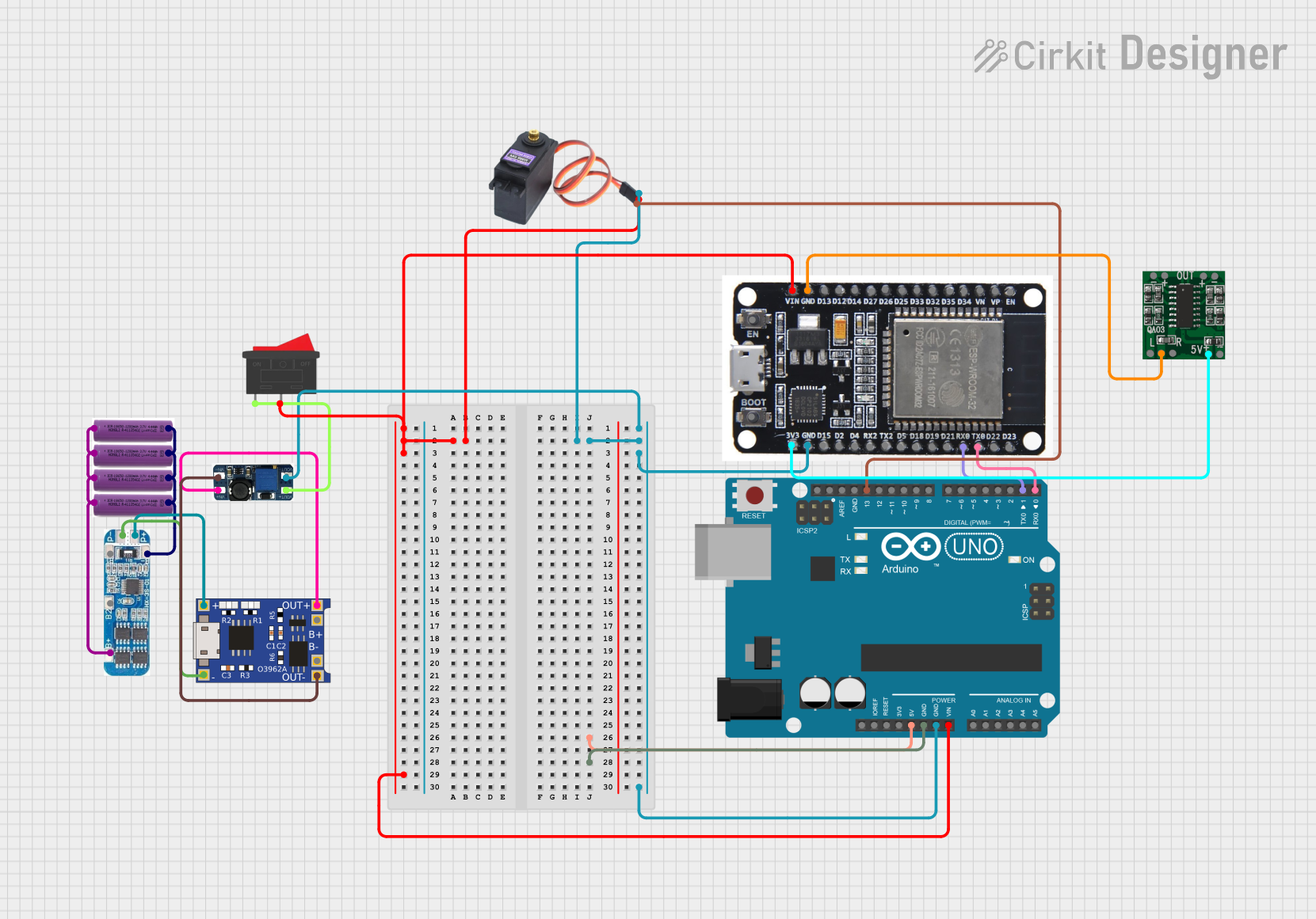

Explore Projects Built with AMS1117 5.0 V
Common Applications
- Powering microcontrollers (e.g., Arduino, ESP8266, Raspberry Pi peripherals)
- Voltage regulation for sensors and modules
- Battery-powered devices
- General-purpose power supply circuits
Technical Specifications
Key Specifications
| Parameter | Value |
|---|---|
| Output Voltage | 5.0 V |
| Input Voltage Range | 6.5 V to 15 V |
| Maximum Output Current | 1 A |
| Dropout Voltage | 1.1 V (at 1 A load) |
| Quiescent Current | 5 mA (typical) |
| Operating Temperature | -40°C to +125°C |
| Package Type | SOT-223, TO-252 |
Pin Configuration
The AMS1117 5.0 V typically comes in a 3-pin SOT-223 or TO-252 package. The pinout is as follows:
| Pin Number | Pin Name | Description |
|---|---|---|
| 1 | ADJ/GND | Ground (GND) |
| 2 | VOUT | Regulated 5.0 V output |
| 3 | VIN | Input voltage (6.5 V to 15 V) |
Usage Instructions
How to Use the AMS1117 5.0 V in a Circuit
- Input Voltage: Connect a DC voltage source (6.5 V to 15 V) to the
VINpin. Ensure the input voltage is at least 1.1 V higher than the desired 5.0 V output to maintain proper regulation. - Output Voltage: Connect the load to the
VOUTpin. The output will be a stable 5.0 V. - Ground Connection: Connect the
ADJ/GNDpin to the ground of the circuit. - Capacitors:
- Place a 10 µF capacitor (electrolytic or ceramic) between
VINandGNDto stabilize the input voltage. - Place a 10 µF capacitor between
VOUTandGNDto ensure stable output voltage and reduce noise.
- Place a 10 µF capacitor (electrolytic or ceramic) between
Important Considerations
- Heat Dissipation: The AMS1117 can generate heat under high current loads. Use a heatsink or ensure proper ventilation if the current exceeds 500 mA.
- Input Voltage Range: Do not exceed the maximum input voltage of 15 V to avoid damaging the regulator.
- Load Current: Ensure the load does not draw more than 1 A, as this is the maximum output current rating.
- Bypass Capacitors: Always use the recommended capacitors to prevent oscillations and ensure stable operation.
Example: Using AMS1117 5.0 V with Arduino UNO
The AMS1117 5.0 V can be used to power an Arduino UNO from a 9 V battery. Below is an example circuit and Arduino code:
Circuit Connections
- Connect the 9 V battery's positive terminal to the
VINpin of the AMS1117. - Connect the battery's negative terminal to the
GNDpin of the AMS1117. - Connect the
VOUTpin of the AMS1117 to the 5 V pin of the Arduino UNO. - Connect the
GNDpin of the AMS1117 to the GND pin of the Arduino UNO.
Arduino Code
// Example code to blink an LED connected to pin 13 of Arduino UNO
// Ensure the AMS1117 is providing a stable 5.0 V to the Arduino

void setup() {
  pinMode(13, OUTPUT); // Set pin 13 as an output pin
}

void loop() {
  digitalWrite(13, HIGH); // Turn the LED on
  delay(1000);            // Wait for 1 second
  digitalWrite(13, LOW);  // Turn the LED off
  delay(1000);            // Wait for 1 second
}
Troubleshooting and FAQs
Common Issues and Solutions
Output Voltage is Not 5.0 V:
- Check the input voltage. Ensure it is at least 6.5 V.
- Verify the capacitors are correctly connected and have the recommended values.
- Ensure the load does not exceed 1 A.
Regulator Overheats:
- Reduce the load current if it exceeds 500 mA.
- Use a heatsink or improve ventilation around the AMS1117.
Oscillations or Noise on Output:
- Ensure the input and output capacitors are placed as close as possible to the AMS1117.
- Use low-ESR capacitors for better performance.
No Output Voltage:
- Verify all connections, especially the ground connection.
- Check if the AMS1117 is damaged due to overvoltage or overcurrent.
FAQs
Q: Can I use the AMS1117 5.0 V with a 5 V input?
A: No, the input voltage must be at least 6.5 V to maintain proper regulation. The dropout voltage is approximately 1.1 V.
Q: What type of capacitors should I use with the AMS1117?
A: Use 10 µF electrolytic or ceramic capacitors with low ESR for both input and output.
Q: Can the AMS1117 power a Raspberry Pi?
A: No, the AMS1117 is not suitable for powering a Raspberry Pi, as it requires more current than the AMS1117 can provide.
Q: Is the AMS1117 suitable for battery-powered applications?
A: Yes, but ensure the input voltage remains within the specified range and consider the quiescent current for battery life.