How to Use GY273: Examples, Pinouts, and Specs
Introduction
The GY-273 is a 3-axis digital compass module based on the HMC5883L sensor. It is designed to measure magnetic fields and determine orientation, making it an essential component in navigation systems, robotics, and various other applications requiring precise directional data. The module communicates via the I2C interface, making it easy to integrate with microcontrollers such as the Arduino UNO.
Explore Projects Built with GY273


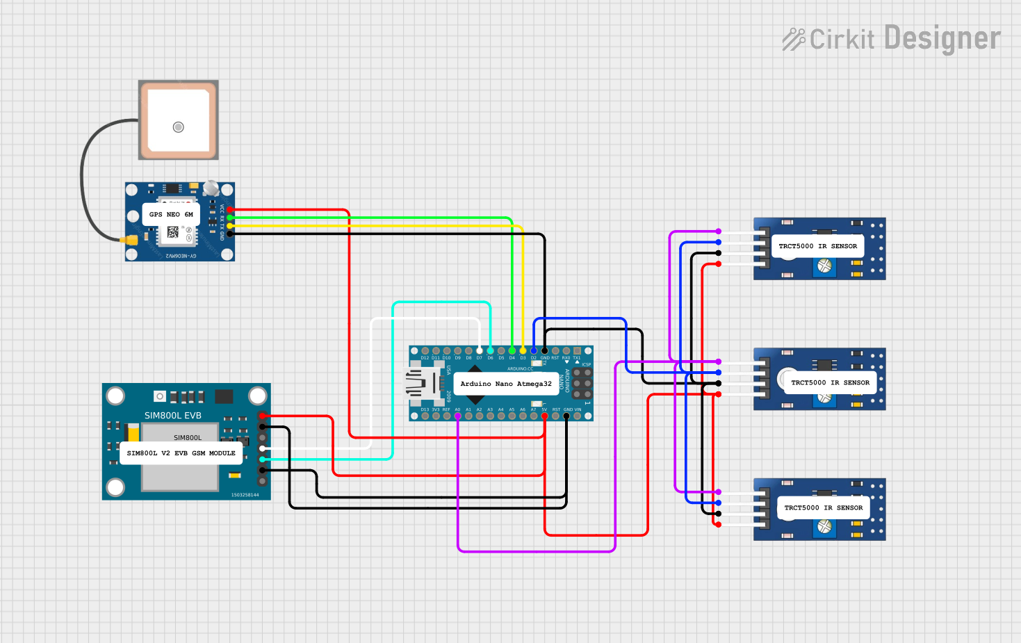

Explore Projects Built with GY273
Technical Specifications
Key Technical Details
| Parameter | Value |
|---|---|
| Operating Voltage | 3.3V to 5V |
| Operating Current | 100 µA |
| Communication | I2C |
| Measurement Range | ±1.3 to ±8 Gauss |
| Resolution | 160 to 1370 LSB/Gauss |
| Dimensions | 14mm x 13mm x 3.5mm |
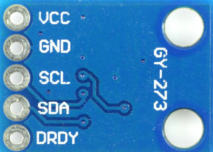
Pin Configuration and Descriptions
| Pin | Name | Description |
|---|---|---|
| 1 | VCC | Power supply (3.3V to 5V) |
| 2 | GND | Ground |
| 3 | SCL | Serial Clock Line for I2C communication |
| 4 | SDA | Serial Data Line for I2C communication |
| 5 | DRDY | Data Ready (optional, not commonly used) |
Usage Instructions
How to Use the GY-273 in a Circuit
- Power Supply: Connect the VCC pin to a 3.3V or 5V power supply and the GND pin to the ground.
- I2C Communication: Connect the SCL pin to the SCL pin on the Arduino (A5 on the UNO) and the SDA pin to the SDA pin on the Arduino (A4 on the UNO).
- Optional Pin: The DRDY pin can be left unconnected if not used.
Important Considerations and Best Practices
- Power Supply: Ensure the module is powered within the specified voltage range to avoid damage.
- I2C Pull-up Resistors: The I2C lines (SCL and SDA) should have pull-up resistors (typically 4.7kΩ) if not already present on the module.
- Magnetic Interference: Keep the module away from strong magnetic fields and ferromagnetic materials to avoid interference.
- Calibration: Perform calibration to improve accuracy, especially if the module is used in a new environment.
Sample Arduino Code
#include <Wire.h>
#include <Adafruit_Sensor.h>
#include <Adafruit_HMC5883_U.h>

// Create an instance of the HMC5883L sensor
Adafruit_HMC5883_Unified mag = Adafruit_HMC5883_Unified(12345);

void setup() {
  Serial.begin(9600);
  // Initialize the sensor
  if (!mag.begin()) {
    Serial.println("Could not find a valid HMC5883 sensor, check wiring!");
    while (1);
  }
}

void loop() {
  // Get a new sensor event
  sensors_event_t event;
  mag.getEvent(&event);

  // Display the results (magnetic vector values are in micro-Tesla (uT))
  Serial.print("X: "); Serial.print(event.magnetic.x); Serial.print("  ");
  Serial.print("Y: "); Serial.print(event.magnetic.y); Serial.print("  ");
  Serial.print("Z: "); Serial.print(event.magnetic.z); Serial.print("  ");
  Serial.println("uT");

  // Delay before the next reading
  delay(500);
}
Troubleshooting and FAQs
Common Issues and Solutions
No Data Output:
- Solution: Check the wiring connections, especially the I2C lines (SCL and SDA). Ensure the module is powered correctly.
Inaccurate Readings:
- Solution: Perform a calibration routine. Ensure the module is away from magnetic interference.
I2C Communication Errors:
- Solution: Verify the pull-up resistors on the I2C lines. Check the I2C address (default is 0x1E) and ensure no address conflicts.
FAQs
Q1: Can the GY-273 be used with a 3.3V microcontroller?
- A1: Yes, the GY-273 can operate with both 3.3V and 5V power supplies.
Q2: How do I calibrate the GY-273?
- A2: Calibration involves rotating the module in all directions and recording the maximum and minimum values for each axis. Use these values to offset the readings.
Q3: What is the default I2C address of the GY-273?
- A3: The default I2C address of the GY-273 is 0x1E.
By following this documentation, users can effectively integrate and utilize the GY-273 3-axis digital compass module in their projects, ensuring accurate and reliable orientation measurements.