How to Use RTC DS1307: Examples, Pinouts, and Specs
Introduction
The DS1307, manufactured by JJY (Part ID: RTC Module), is a real-time clock (RTC) chip designed to keep track of the current time and date. It communicates with microcontrollers using the I2C protocol and features a battery backup, ensuring that the time and date are maintained even during power outages. This makes it an essential component for time-sensitive applications.
Explore Projects Built with RTC DS1307

Explore Projects Built with RTC DS1307
Common Applications and Use Cases
- Digital clocks and timers
- Data logging systems
- Home automation systems
- Alarm systems
- Embedded systems requiring timekeeping functionality
Technical Specifications
The DS1307 RTC module is a versatile and reliable timekeeping solution. Below are its key technical specifications:
| Parameter | Value |
|---|---|
| Operating Voltage | 4.5V to 5.5V |
| Backup Battery Voltage | 3.0V (typical) |
| Communication Protocol | I2C (Inter-Integrated Circuit) |
| Timekeeping Accuracy | ±2 seconds/day (at 25°C) |
| Operating Temperature | -40°C to +85°C |
| Current Consumption | 1.5µA (with battery backup, typical) |
| Time Format | 12-hour or 24-hour format |
| Calendar Support | Automatic leap year compensation (up to 2100) |
| Memory | 56 bytes of non-volatile RAM |
Pin Configuration and Descriptions
The DS1307 RTC module typically has 8 pins. Below is the pinout and description:
| Pin | Name | Description |
|---|---|---|
| 1 | X1 | 32.768 kHz crystal oscillator input. Connect to an external crystal. |
| 2 | X2 | 32.768 kHz crystal oscillator output. Connect to an external crystal. |
| 3 | VBAT | Backup battery input. Connect to a 3V coin cell battery for power backup. |
| 4 | GND | Ground pin. Connect to the ground of the circuit. |
| 5 | SDA | Serial Data Line for I2C communication. |
| 6 | SCL | Serial Clock Line for I2C communication. |
| 7 | NC | Not connected. Leave this pin unconnected. |
| 8 | VCC | Power supply input. Connect to a 5V DC source. |
Usage Instructions
The DS1307 RTC module is straightforward to use in a circuit. Below are the steps and considerations for proper usage:
Connecting the DS1307 to a Microcontroller
- Power Supply: Connect the
VCCpin to a 5V power source and theGNDpin to the ground. - Backup Battery: Attach a 3V coin cell battery to the
VBATpin to ensure timekeeping during power outages. - I2C Communication:
- Connect the
SDApin to the microcontroller's I2C data line. - Connect the
SCLpin to the microcontroller's I2C clock line.
- Connect the
- Crystal Oscillator: Attach a 32.768 kHz crystal between the
X1andX2pins.
Important Considerations
- Use pull-up resistors (typically 4.7kΩ) on the
SDAandSCLlines for proper I2C communication. - Ensure the backup battery is installed correctly to maintain timekeeping during power loss.
- Avoid placing the module near high-frequency components to minimize interference with the crystal oscillator.
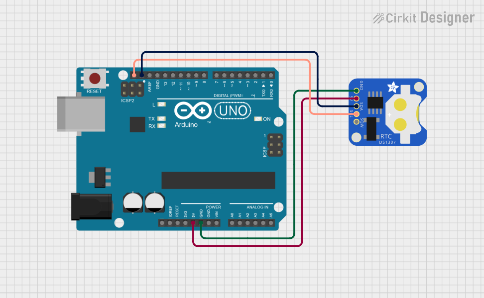
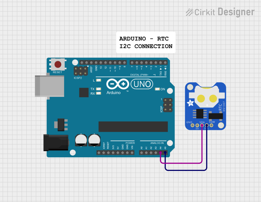
Example: Using DS1307 with Arduino UNO
Below is an example of how to interface the DS1307 RTC module with an Arduino UNO using the RTClib library.
Circuit Diagram
- Connect
VCCto the Arduino's 5V pin. - Connect
GNDto the Arduino's GND pin. - Connect
SDAto the Arduino's A4 pin. - Connect
SCLto the Arduino's A5 pin.
Arduino Code
#include <Wire.h>
#include <RTClib.h>

// Create an RTC_DS1307 object to interact with the DS1307 module
RTC_DS1307 rtc;

void setup() {
  Serial.begin(9600); // Initialize serial communication at 9600 baud
  Wire.begin();       // Initialize I2C communication

  if (!rtc.begin()) {
    // Check if the RTC module is connected
    Serial.println("Couldn't find RTC");
    while (1); // Halt the program if the RTC is not found
  }

  if (!rtc.isrunning()) {
    // Check if the RTC is running and set the time if not
    Serial.println("RTC is NOT running, setting the time...");
    rtc.adjust(DateTime(F(__DATE__), F(__TIME__)));
    // Sets the RTC to the date & time the sketch was compiled
  }
}

void loop() {
  DateTime now = rtc.now(); // Get the current date and time

  // Print the current date and time to the serial monitor
  Serial.print(now.year(), DEC);
  Serial.print('/');
  Serial.print(now.month(), DEC);
  Serial.print('/');
  Serial.print(now.day(), DEC);
  Serial.print(" ");
  Serial.print(now.hour(), DEC);
  Serial.print(':');
  Serial.print(now.minute(), DEC);
  Serial.print(':');
  Serial.print(now.second(), DEC);
  Serial.println();

  delay(1000); // Wait for 1 second before updating the time
}
Troubleshooting and FAQs
Common Issues and Solutions
RTC Not Detected by Microcontroller
- Cause: Incorrect I2C connections or missing pull-up resistors.
- Solution: Verify the
SDAandSCLconnections and ensure pull-up resistors are in place.
Time Resets After Power Loss
- Cause: Backup battery is not connected or is depleted.
- Solution: Check the
VBATconnection and replace the battery if necessary.
Inaccurate Timekeeping
- Cause: Faulty or improperly connected crystal oscillator.
- Solution: Ensure the 32.768 kHz crystal is securely connected to the
X1andX2pins.
Interference with I2C Communication
- Cause: Noise or interference from nearby components.
- Solution: Use shorter wires for I2C connections and avoid placing the module near high-frequency components.
FAQs
Q: Can the DS1307 operate without a backup battery?
A: Yes, but the time and date will reset whenever the main power is lost.
Q: What is the maximum length of the I2C bus for the DS1307?
A: The I2C bus length should typically not exceed 1 meter to ensure reliable communication.
Q: Can the DS1307 handle daylight saving time adjustments?
A: No, the DS1307 does not have built-in support for daylight saving time. Adjustments must be handled in software.
Q: Is the DS1307 compatible with 3.3V microcontrollers?
A: The DS1307 requires a 5V power supply, but its I2C lines can be level-shifted to work with 3.3V microcontrollers.