How to Use STM32 L432KC: Examples, Pinouts, and Specs
Introduction
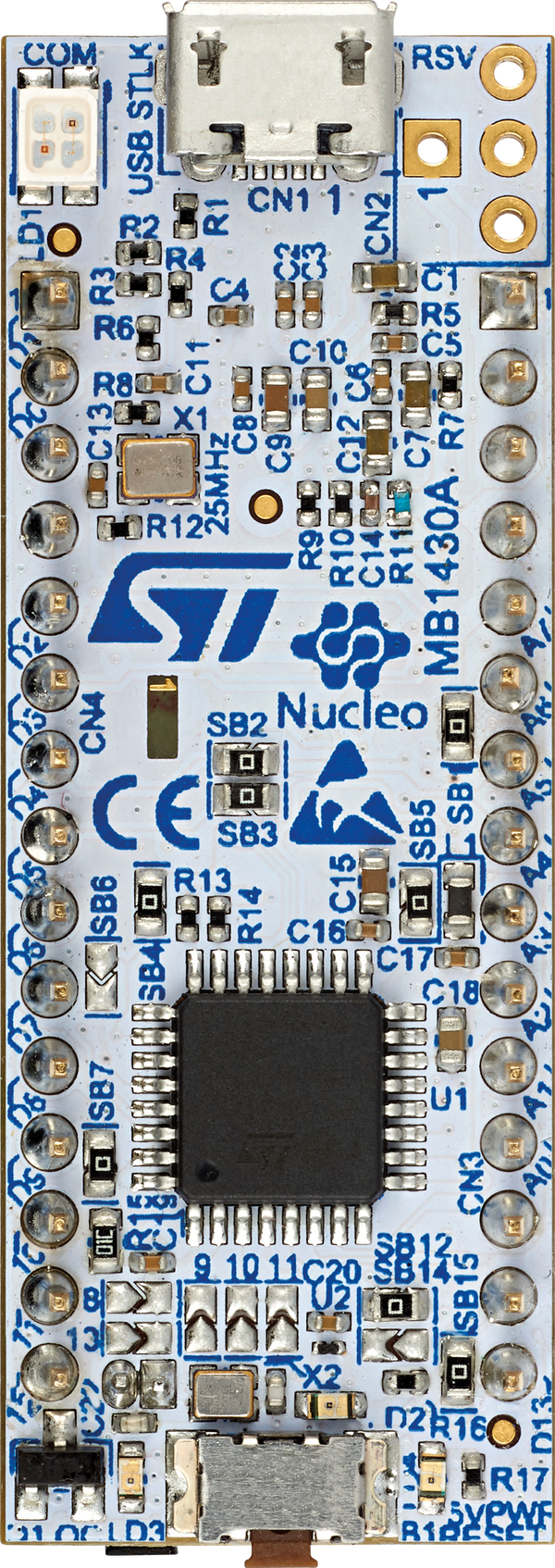
The STM32 L432KC is a low-power microcontroller from STMicroelectronics, built around the ARM Cortex-M4 core. It operates at a maximum clock speed of 80 MHz and features 256 KB of flash memory and 32 KB of SRAM. This microcontroller is designed for energy-efficient applications, making it ideal for battery-powered devices, IoT applications, and portable electronics. It includes a wide range of peripherals such as analog-to-digital converters (ADCs), timers, and communication interfaces like I2C, SPI, and UART.
Explore Projects Built with STM32 L432KC


Explore Projects Built with STM32 L432KC
Common Applications
- Wearable devices
- Internet of Things (IoT) applications
- Low-power data acquisition systems
- Portable medical devices
- Industrial automation and control systems
Technical Specifications
The STM32 L432KC offers a robust set of features tailored for low-power and high-performance applications. Below are its key technical specifications:
General Specifications
| Feature | Specification |
|---|---|
| Core | ARM Cortex-M4 with FPU |
| Maximum Clock Speed | 80 MHz |
| Flash Memory | 256 KB |
| SRAM | 32 KB |
| Operating Voltage | 1.8V to 3.6V |
| Power Modes | Sleep, Stop, Standby |
| Package | NUCLEO-32 (32-pin) |
Peripherals
| Peripheral | Details |
|---|---|
| ADC | 12-bit, up to 16 channels |
| Timers | 7 timers (including advanced control) |
| Communication Interfaces | I2C, SPI, UART, USART, CAN |
| GPIO | Up to 26 GPIO pins |
| PWM | Supported |
Pin Configuration
The STM32 L432KC is available in a 32-pin package. Below is the pinout description:
| Pin Number | Pin Name | Functionality |
|---|---|---|
| 1 | PA0 | GPIO, ADC_IN0, TIM2_CH1, WKUP1 |
| 2 | PA1 | GPIO, ADC_IN1, TIM2_CH2 |
| 3 | PA2 | GPIO, USART2_TX, ADC_IN2, TIM2_CH3 |
| 4 | PA3 | GPIO, USART2_RX, ADC_IN3, TIM2_CH4 |
| ... | ... | ... (Refer to the datasheet for full) |
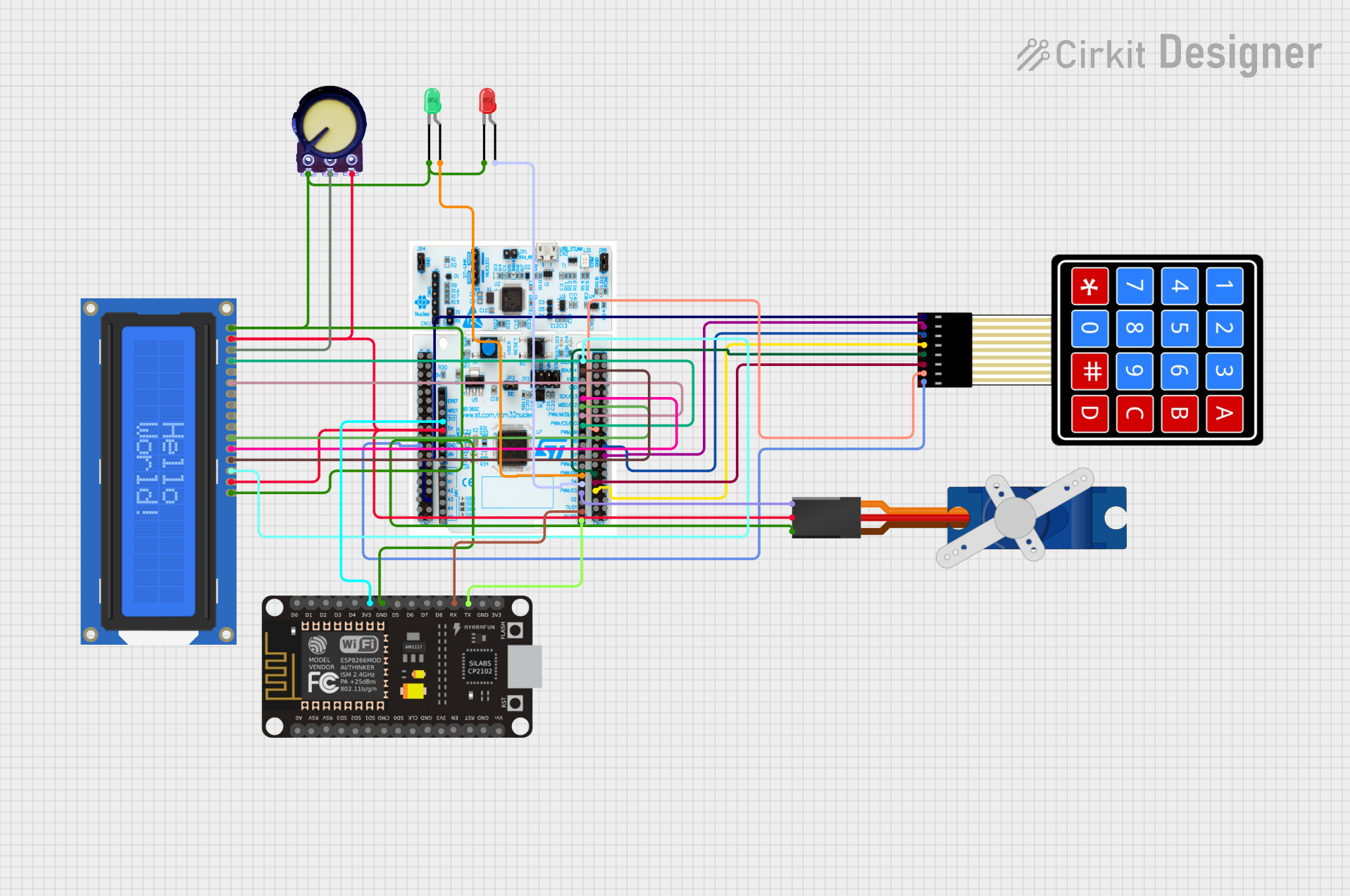
Usage Instructions
The STM32 L432KC can be used in a variety of applications, thanks to its versatile peripherals and low-power features. Below are the steps and considerations for using this microcontroller in a circuit:
Basic Setup
- Power Supply: Ensure the microcontroller is powered within its operating voltage range (1.8V to 3.6V). A 3.3V regulator is commonly used.
- Clock Configuration: The STM32 L432KC supports internal and external clock sources. For precise timing, connect an external crystal oscillator to the appropriate pins.
- Programming Interface: Use the SWD (Serial Wire Debug) interface for programming and debugging. Tools like ST-Link or J-Link are compatible.
- Reset Pin: Connect a pull-up resistor (typically 10 kΩ) to the NRST pin to ensure proper reset functionality.
Example: Blinking an LED
Below is an example of how to blink an LED connected to pin PA5 using the STM32CubeIDE:
#include "stm32l4xx_hal.h"

// Define the GPIO pin for the LED
#define LED_PIN GPIO_PIN_5
#define LED_PORT GPIOA

void SystemClock_Config(void);
void GPIO_Init(void);

int main(void) {
    HAL_Init();                  // Initialize the HAL library
    SystemClock_Config();        // Configure the system clock
    GPIO_Init();                 // Initialize GPIO for the LED

    while (1) {
        HAL_GPIO_TogglePin(LED_PORT, LED_PIN); // Toggle the LED state
        HAL_Delay(500);                        // Wait for 500 ms
    }
}

void GPIO_Init(void) {
    __HAL_RCC_GPIOA_CLK_ENABLE(); // Enable GPIOA clock

    GPIO_InitTypeDef GPIO_InitStruct = {0};
    GPIO_InitStruct.Pin = LED_PIN;            // Configure the LED pin
    GPIO_InitStruct.Mode = GPIO_MODE_OUTPUT_PP; // Set as push-pull output
    GPIO_InitStruct.Pull = GPIO_NOPULL;       // No pull-up or pull-down
    GPIO_InitStruct.Speed = GPIO_SPEED_FREQ_LOW; // Low speed
    HAL_GPIO_Init(LED_PORT, &GPIO_InitStruct);
}

void SystemClock_Config(void) {
    // Configure the system clock (default settings for simplicity)
    RCC_OscInitTypeDef RCC_OscInitStruct = {0};
    RCC_ClkInitTypeDef RCC_ClkInitStruct = {0};

    RCC_OscInitStruct.OscillatorType = RCC_OSCILLATORTYPE_MSI;
    RCC_OscInitStruct.MSIState = RCC_MSI_ON;
    RCC_OscInitStruct.MSICalibrationValue = RCC_MSICALIBRATION_DEFAULT;
    RCC_OscInitStruct.MSIClockRange = RCC_MSIRANGE_6;
    RCC_OscInitStruct.PLL.PLLState = RCC_PLL_NONE;
    HAL_RCC_OscConfig(&RCC_OscInitStruct);

    RCC_ClkInitStruct.ClockType = RCC_CLOCKTYPE_HCLK | RCC_CLOCKTYPE_SYSCLK
                                  | RCC_CLOCKTYPE_PCLK1 | RCC_CLOCKTYPE_PCLK2;
    RCC_ClkInitStruct.SYSCLKSource = RCC_SYSCLKSOURCE_MSI;
    RCC_ClkInitStruct.AHBCLKDivider = RCC_SYSCLK_DIV1;
    RCC_ClkInitStruct.APB1CLKDivider = RCC_HCLK_DIV1;
    RCC_ClkInitStruct.APB2CLKDivider = RCC_HCLK_DIV1;
    HAL_RCC_ClockConfig(&RCC_ClkInitStruct, FLASH_LATENCY_0);
}
Best Practices
- Use decoupling capacitors (e.g., 0.1 µF) near the power pins to reduce noise.
- Avoid leaving unused pins floating; configure them as inputs with pull-up or pull-down resistors.
- Use proper ESD protection for GPIO pins exposed to external connections.
Troubleshooting and FAQs
Common Issues
Microcontroller Not Responding
- Cause: Incorrect power supply or clock configuration.
- Solution: Verify the power supply voltage and ensure the clock source is configured correctly.
Programming Failure
- Cause: Faulty SWD connection or incorrect firmware.
- Solution: Check the SWD connections and ensure the correct firmware is being flashed.
Peripheral Not Working
- Cause: Incorrect pin configuration or missing clock enable.
- Solution: Double-check the pin configuration and ensure the peripheral clock is enabled in the code.
FAQs
Q: Can the STM32 L432KC operate at 5V?
A: No, the maximum operating voltage is 3.6V. Use a voltage regulator to step down from 5V to 3.3V.
Q: How do I reduce power consumption?
A: Use the low-power modes (Sleep, Stop, or Standby) and disable unused peripherals.
Q: What development tools are compatible with the STM32 L432KC?
A: STM32CubeIDE, Keil MDK, IAR Embedded Workbench, and GCC-based toolchains are supported.
Q: Can I use the STM32 L432KC with Arduino IDE?
A: Yes, with the STM32duino core installed, the STM32 L432KC can be programmed using the Arduino IDE.