How to Use DC-DC BOOST CONVERTOR: Examples, Pinouts, and Specs
Introduction
A DC-DC Boost Converter is an essential electronic component that elevates a lower direct current (DC) input voltage to a higher output voltage. This type of power converter is widely used in various applications, including but not limited to battery-powered devices, portable electronics, and systems that require voltage levels not provided by the main power source.
Explore Projects Built with DC-DC BOOST CONVERTOR


Explore Projects Built with DC-DC BOOST CONVERTOR
Common Applications and Use Cases
- Powering devices that require a higher voltage than the available battery voltage
- Solar power systems where the converter steps up the voltage from solar panels
- Electric vehicles to boost battery voltage for high-power requirements
- Portable electronics to maintain a stable voltage as the battery discharges
- LED drivers where a constant current is required at a higher voltage
Technical Specifications
Key Technical Details
- Input Voltage Range: Typically 2V to 15V DC
- Output Voltage Range: Typically 5V to 35V DC
- Maximum Output Current: Depending on the model, can range from 1A to 5A
- Efficiency: Up to 90-95% under optimal conditions
- Switching Frequency: Usually in the range of 100 kHz to 1 MHz
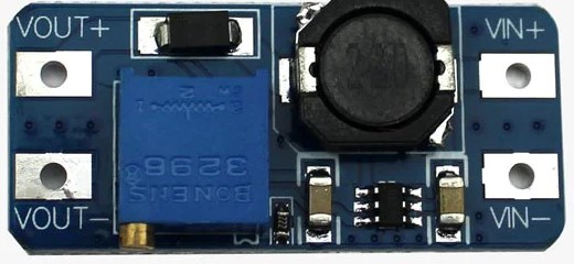
Pin Configuration and Descriptions
| Pin Number | Name | Description |
|---|---|---|
| 1 | VIN | Input voltage to the converter. Connect to the DC power source. |
| 2 | GND | Ground reference for the circuit. Connect to the power source ground and load ground. |
| 3 | VOUT | Output voltage from the converter. Connect to the load device. |
| 4 | EN | Enable pin to turn the converter on or off. Typically pulled high to enable. |
| 5 | FB | Feedback pin used for voltage regulation. Often connected to a voltage divider. |
Usage Instructions
How to Use the Component in a Circuit
Connecting Power Source:
- Connect the positive terminal of your DC power source to the VIN pin.
- Connect the negative terminal to the GND pin.
Setting Output Voltage:
- If the converter has an adjustable output, set the desired voltage using the onboard potentiometer or by configuring the feedback network appropriately.
Enabling the Converter:
- If there is an enable pin (EN), ensure it is pulled high to activate the converter.
Connecting the Load:
- Connect the positive terminal of your load to the VOUT pin.
- Connect the negative terminal of your load to the GND pin.
Important Considerations and Best Practices
- Heat Dissipation: Ensure adequate cooling for the converter, as efficiency losses can lead to heat generation.
- Input Voltage: Do not exceed the maximum input voltage rating to prevent damage.
- Output Load: Avoid exceeding the maximum output current to maintain performance and reliability.
- Filtering: Use capacitors at the input and output for voltage smoothing and to reduce noise.
- Shielding: Minimize electromagnetic interference (EMI) by placing the converter away from sensitive components or using shielding techniques.
Troubleshooting and FAQs
Common Issues Users Might Face
- Insufficient Output Voltage: Check the input voltage and adjust the feedback network if necessary.
- Overheating: Ensure proper heat dissipation and verify that the load does not exceed the converter's maximum current rating.
- Noise Issues: Add filtering capacitors or inductors to reduce EMI and ripple.
Solutions and Tips for Troubleshooting
- Output Voltage Adjustment: If the output voltage is not as expected, recalibrate the feedback network or potentiometer.
- Thermal Management: Attach a heatsink or improve airflow around the converter to manage excess heat.
- Check Connections: Loose or poor connections can cause instability. Verify all connections are secure.
FAQs
Q: Can I use the boost converter without a load? A: It is not recommended to operate the converter without a load, as this can lead to high voltage spikes.
Q: What is the typical efficiency of a DC-DC boost converter? A: Efficiency can range from 80% to 95%, depending on the input and output voltages, load current, and quality of the converter.
Q: How do I choose the right inductor and capacitor for my application? A: The choice depends on the switching frequency, current requirements, and desired ripple. Consult the datasheet or a power electronics design guide for recommendations.
Example Code for Arduino UNO Connection
// Example code to control a DC-DC Boost Converter with an Arduino UNO
// This example assumes the use of an enable pin on the boost converter.

const int enablePin = 9; // Connect to the EN pin of the boost converter

void setup() {
  pinMode(enablePin, OUTPUT);
  digitalWrite(enablePin, LOW); // Start with the converter disabled
}

void loop() {
  // Enable the boost converter
  digitalWrite(enablePin, HIGH);
  delay(5000); // Wait for 5 seconds

  // Disable the boost converter
  digitalWrite(enablePin, LOW);
  delay(5000); // Wait for 5 seconds
}
Note: The above code is a simple example to demonstrate enabling and disabling the boost converter using an Arduino UNO. The actual implementation may vary based on the specific requirements of your application. Always refer to the datasheet of the boost converter for accurate control methods and pin configurations.