How to Use Trema Mega Tail Shield: Examples, Pinouts, and Specs
Introduction
The Trema Mega Tail Shield by iarduino.ru is a versatile expansion board designed to enhance the functionality of microcontrollers, such as the Arduino Mega. This shield provides additional connectivity options and features, including support for sensors, displays, and communication interfaces. It is an ideal solution for projects requiring multiple peripherals or complex hardware setups.
Explore Projects Built with Trema Mega Tail Shield
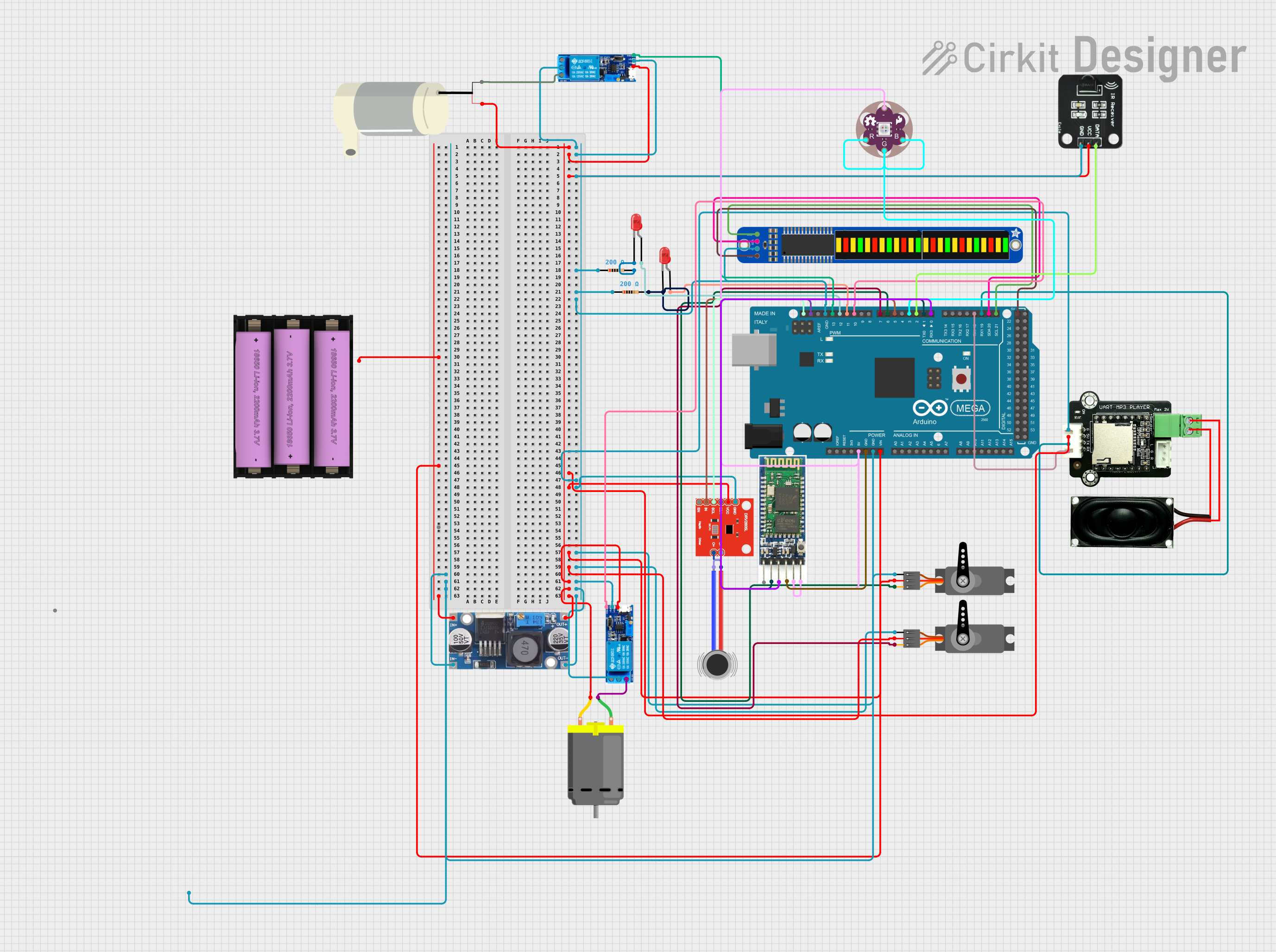

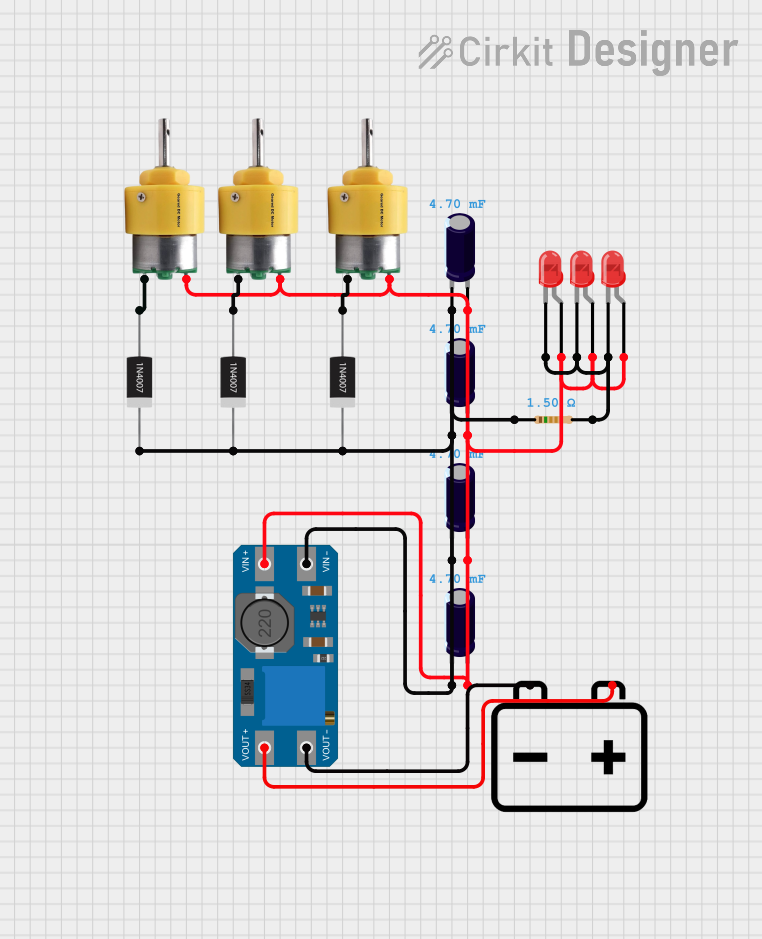
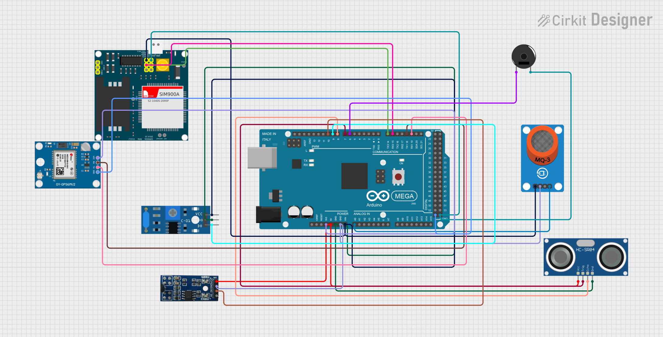
Explore Projects Built with Trema Mega Tail Shield
Common Applications and Use Cases
- Robotics and automation systems
- IoT (Internet of Things) devices
- Prototyping with multiple sensors and actuators
- Projects requiring advanced communication protocols (e.g., I2C, SPI, UART)
- Interactive displays and user interfaces
Technical Specifications
The Trema Mega Tail Shield is designed to seamlessly integrate with the Arduino Mega and similar microcontrollers. Below are its key technical details:
General Specifications
| Parameter | Value |
|---|---|
| Compatible Microcontrollers | Arduino Mega, Arduino Due |
| Operating Voltage | 5V (from Arduino Mega) |
| Communication Interfaces | I2C, SPI, UART |
| Supported Modules | Sensors, displays, actuators |
| Dimensions | Matches Arduino Mega form factor |
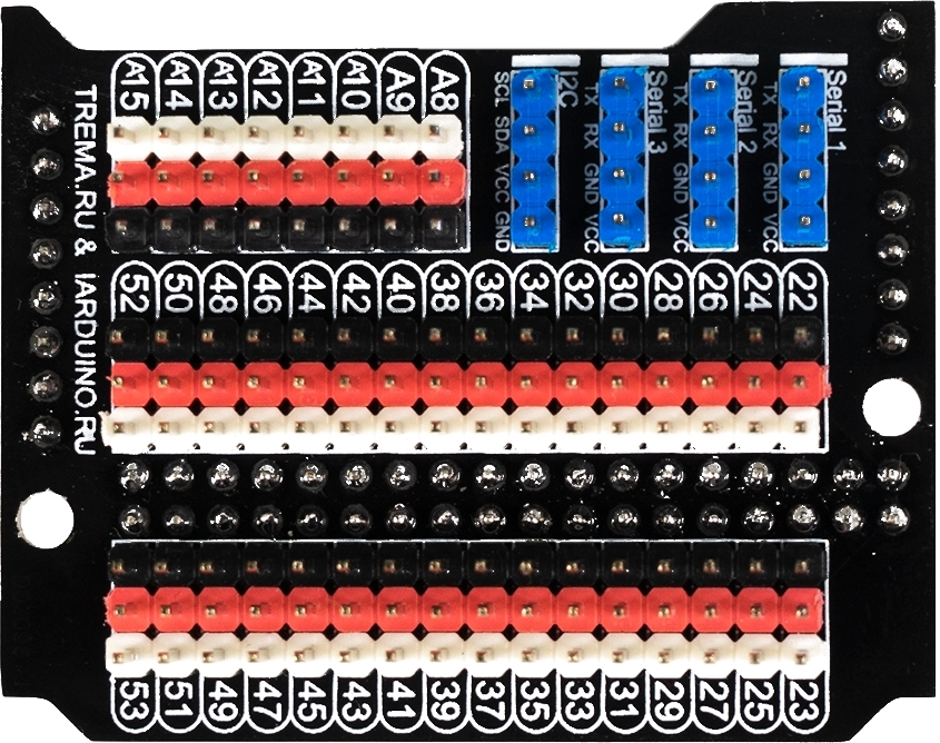
Pin Configuration and Descriptions
The Trema Mega Tail Shield provides easy access to the Arduino Mega's pins while adding additional functionality. Below is the pin configuration:
| Pin Name | Description |
|---|---|
| I2C (SCL/SDA) | Dedicated pins for I2C communication with sensors and modules |
| SPI (MISO/MOSI/SCK) | SPI interface for high-speed communication with peripherals |
| UART (TX/RX) | Serial communication pins for connecting to external devices |
| Digital I/O | Standard digital input/output pins for general-purpose use |
| Analog I/O | Analog input pins for reading sensor data |
| Power Pins | 5V, 3.3V, and GND pins for powering external modules |
Usage Instructions
The Trema Mega Tail Shield is designed for plug-and-play functionality with the Arduino Mega. Follow these steps to use the shield effectively:
Step 1: Installation
- Align the shield with the Arduino Mega's pin headers.
- Carefully press the shield onto the Arduino Mega, ensuring all pins are properly connected.
Step 2: Connecting Peripherals
- Sensors: Connect I2C, SPI, or analog sensors to the corresponding pins on the shield.
- Displays: Attach compatible displays (e.g., OLED, LCD) to the I2C or SPI interface.
- Actuators: Use the digital I/O pins to control motors, relays, or other actuators.
Step 3: Programming
Write your Arduino sketch to interact with the connected peripherals. Below is an example code snippet for using an I2C sensor with the Trema Mega Tail Shield:
#include <Wire.h> // Include the Wire library for I2C communication

void setup() {
  Wire.begin(); // Initialize I2C communication
  Serial.begin(9600); // Start serial communication for debugging
  Serial.println("Trema Mega Tail Shield: I2C Example");
}

void loop() {
  Wire.beginTransmission(0x68); // Start communication with a device at address 0x68
  Wire.write(0x00); // Send a command or register address
  Wire.endTransmission(); // End the transmission

  Wire.requestFrom(0x68, 2); // Request 2 bytes of data from the device
  if (Wire.available() == 2) { // Check if 2 bytes are available
    int data = Wire.read() << 8 | Wire.read(); // Read and combine the data
    Serial.print("Sensor Data: ");
    Serial.println(data); // Print the sensor data
  }
  delay(1000); // Wait for 1 second before the next reading
}
Important Considerations and Best Practices
- Ensure the shield is securely connected to the Arduino Mega to avoid loose connections.
- Verify the operating voltage of connected peripherals to prevent damage.
- Use pull-up resistors for I2C lines if required by your sensors or modules.
- Avoid connecting high-current devices directly to the shield; use external power supplies if needed.
Troubleshooting and FAQs
Common Issues and Solutions
Issue: The shield is not detected by the Arduino IDE.
- Solution: Ensure the shield is properly seated on the Arduino Mega. Check for bent or misaligned pins.
Issue: I2C devices are not responding.
- Solution: Verify the I2C address of the device and ensure it matches the address in your code. Check for proper pull-up resistors on the I2C lines.
Issue: SPI communication is unreliable.
- Solution: Ensure proper grounding between the shield and connected devices. Check the SPI clock speed and adjust if necessary.
Issue: Peripherals are not receiving power.
- Solution: Confirm that the shield is receiving power from the Arduino Mega. Check the power pins for proper voltage levels.
FAQs
Q1: Can the Trema Mega Tail Shield be used with the Arduino Uno?
A1: No, the shield is specifically designed for the Arduino Mega and similar boards with a larger form factor.
Q2: How many I2C devices can be connected to the shield?
A2: The number of I2C devices depends on their unique addresses. Typically, up to 127 devices can be connected, provided they have unique addresses.
Q3: Does the shield support 3.3V peripherals?
A3: Yes, the shield provides a 3.3V power pin for peripherals. However, ensure the logic levels are compatible with the Arduino Mega's 5V logic.
Q4: Can I stack other shields on top of the Trema Mega Tail Shield?
A4: Yes, the shield supports stacking, but ensure the additional shield does not block access to required pins or interfere with connected peripherals.
By following this documentation, you can effectively utilize the Trema Mega Tail Shield to expand the capabilities of your Arduino Mega projects.