How to Use nextion 5 inch: Examples, Pinouts, and Specs
Introduction
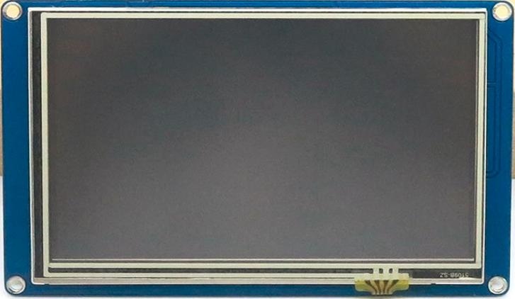
The Nextion 5-inch TFT display module is a powerful and user-friendly graphical user interface (GUI) solution. It features a 5-inch resistive or capacitive touchscreen, a built-in microcontroller, and a simple UART interface for communication. Designed for seamless integration, the Nextion display allows developers to create interactive and visually appealing interfaces for their projects without requiring extensive programming knowledge.
Explore Projects Built with nextion 5 inch
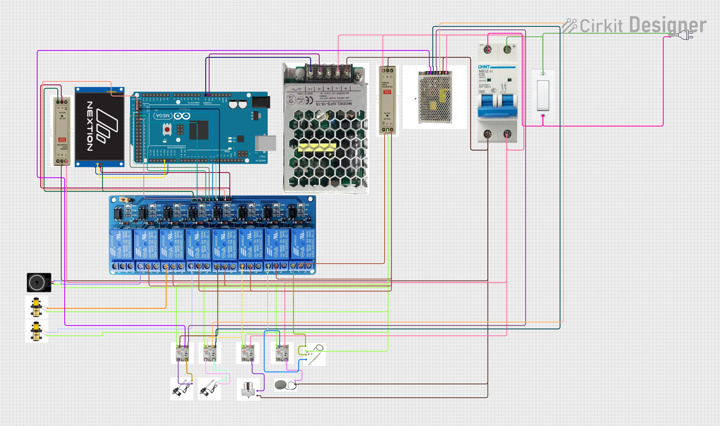


Explore Projects Built with nextion 5 inch
Common Applications and Use Cases
- Home automation systems
- Industrial control panels
- IoT devices with graphical interfaces
- Medical devices
- Educational and hobbyist projects
- Automotive dashboards
Technical Specifications
Below are the key technical details of the Nextion 5-inch TFT display module:
| Specification | Details |
|---|---|
| Display Type | TFT LCD with resistive or capacitive touchscreen |
| Screen Size | 5 inches |
| Resolution | 800 x 480 pixels |
| Color Depth | 65K (16-bit RGB) |
| Communication Interface | UART (TTL, 3.3V logic level) |
| Input Voltage | 4.75V to 7V |
| Power Consumption | 500mA (typical) |
| Operating Temperature | -20°C to 70°C |
| Storage Temperature | -30°C to 85°C |
| Flash Memory | 16MB (for storing GUI resources) |
| RAM | 3584 bytes |
| Touch Panel | Resistive or capacitive (depending on the model) |
| Dimensions | 133.5mm x 85.4mm x 7.2mm |
Pin Configuration and Descriptions
The Nextion 5-inch display module has a 4-pin interface for power and communication:
| Pin | Name | Description |
|---|---|---|
| 1 | GND | Ground connection |
| 2 | VCC | Power supply input (4.75V to 7V) |
| 3 | TX | UART Transmit (data sent from the display to the host microcontroller) |
| 4 | RX | UART Receive (data sent from the host microcontroller to the display) |
Usage Instructions
How to Use the Component in a Circuit
- Powering the Display: Connect the
VCCpin to a 5V power source and theGNDpin to ground. - UART Communication: Connect the
TXpin of the display to theRXpin of the host microcontroller (e.g., Arduino UNO) and theRXpin of the display to theTXpin of the microcontroller. - Programming the Display:
- Use the Nextion Editor software to design the GUI. This software allows you to add buttons, sliders, text fields, and other graphical elements.
- Export the GUI project as a
.tftfile and upload it to the display using a microSD card or via UART.
- Interfacing with a Microcontroller:
- Use UART commands to send and receive data between the microcontroller and the display.
- For example, you can send commands to update text fields, change pages, or read touch input.
Important Considerations and Best Practices
- Power Supply: Ensure a stable 5V power supply to avoid display flickering or malfunction.
- UART Logic Levels: The display operates at 3.3V logic levels. If your microcontroller uses 5V logic (e.g., Arduino UNO), use a voltage divider or level shifter to prevent damage.
- GUI Design: Optimize your GUI design to minimize resource usage and improve performance.
- SD Card Compatibility: Use a FAT32-formatted microSD card for uploading GUI files.
Example: Connecting to an Arduino UNO
Below is an example of how to interface the Nextion 5-inch display with an Arduino UNO:
Circuit Connections
VCC→ 5V on ArduinoGND→ GND on ArduinoTX→ Pin 2 on Arduino (via voltage divider for 3.3V logic)RX→ Pin 3 on Arduino
Arduino Code Example
#include <SoftwareSerial.h>

// Define software serial pins for communication with the Nextion display
SoftwareSerial nextion(2, 3); // RX, TX

void setup() {
  // Initialize serial communication with the Nextion display
  nextion.begin(9600); // Default baud rate for Nextion displays
  Serial.begin(9600);  // For debugging via the Serial Monitor

  // Send a command to the Nextion display to set the text of a component
  nextion.print("t0.txt=\"Hello, World!\""); // Update text field t0
  nextion.write(0xFF); // End of command
  nextion.write(0xFF); // Required by Nextion protocol
  nextion.write(0xFF); // Required by Nextion protocol
}

void loop() {
  // Example: Read touch events from the Nextion display
  if (nextion.available()) {
    String response = "";
    while (nextion.available()) {
      response += (char)nextion.read();
    }
    Serial.println("Response from Nextion: " + response);
  }
}
Troubleshooting and FAQs
Common Issues and Solutions
Display Not Powering On:
- Ensure the
VCCandGNDpins are properly connected. - Verify that the power supply provides sufficient current (at least 500mA).
- Ensure the
No Communication Between Display and Microcontroller:
- Check the UART connections (
TXandRX) and ensure they are not swapped. - Confirm that the baud rate in your code matches the display's baud rate.
- Check the UART connections (
Touch Input Not Responding:
- Verify that the correct touch panel type (resistive or capacitive) is selected in the Nextion Editor.
- Ensure the touch panel is not physically damaged.
GUI Not Loading:
- Check that the
.tftfile is correctly exported and uploaded to the display. - Ensure the microSD card is formatted as FAT32 and is compatible with the display.
- Check that the
FAQs
Q: Can I use the Nextion display with a Raspberry Pi?
A: Yes, the Nextion display can be connected to a Raspberry Pi via UART. Use the GPIO pins for communication and ensure proper voltage level shifting if necessary.
Q: How do I reset the display to factory settings?
A: You can reset the display by uploading a blank .tft file or using the reset command in the Nextion Editor.
Q: What is the maximum cable length for UART communication?
A: For reliable communication, keep the cable length under 1 meter. Use shielded cables for longer distances.
Q: Can I use the display without a microcontroller?
A: Yes, the Nextion display can operate independently by using its built-in microcontroller to handle GUI interactions.