How to Use RS-485-USB: Examples, Pinouts, and Specs
Introduction
The RS-485-USB converter is a versatile electronic component designed to bridge the gap between devices using the RS-485 communication standard and modern USB interfaces. It enables seamless data transfer between RS-485 serial devices and computers, making it an essential tool for industrial automation, data acquisition systems, and other serial communication applications.
Explore Projects Built with RS-485-USB

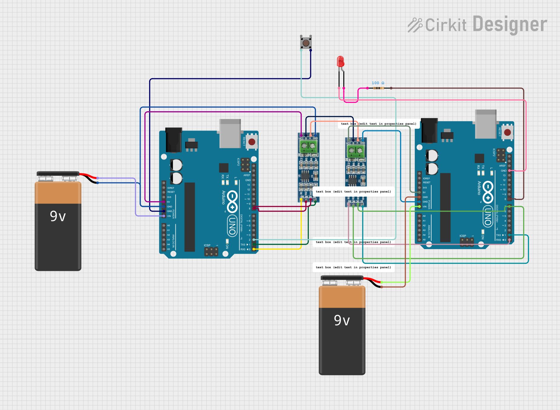
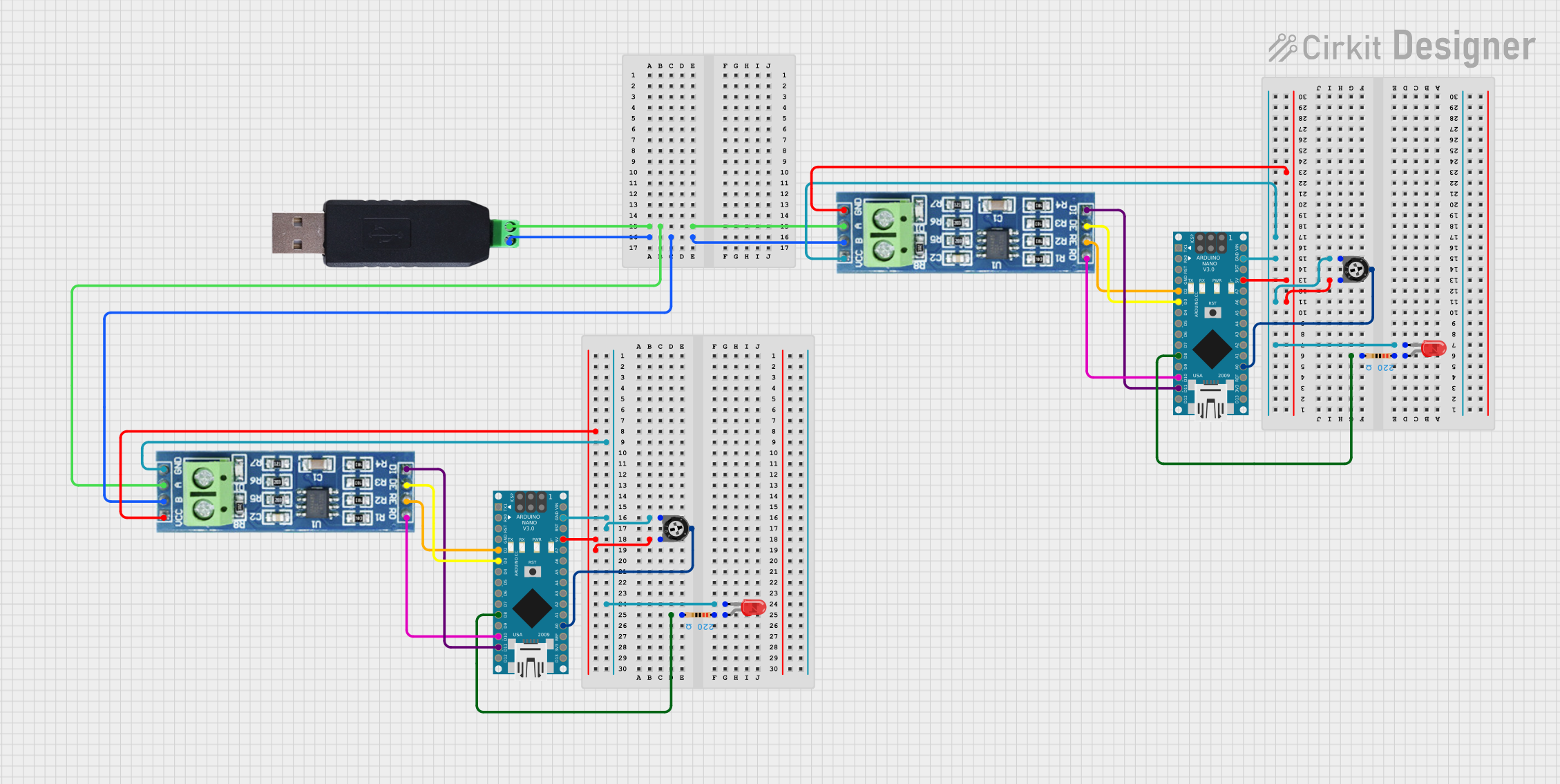

Explore Projects Built with RS-485-USB
Common Applications and Use Cases
- Industrial automation systems for connecting PLCs and sensors to computers.
- Data acquisition systems for monitoring and logging data from RS-485 devices.
- Home automation systems for integrating RS-485-based devices with PCs.
- Debugging and testing RS-485 communication protocols.
- Connecting legacy RS-485 devices to modern USB-enabled computers.
Technical Specifications
Key Technical Details
- Input Voltage (USB side): 5V (via USB port)
- Communication Standard: RS-485 (half-duplex)
- USB Interface: USB 2.0 (compatible with USB 1.1 and USB 3.0)
- Baud Rate: Up to 3 Mbps
- Operating Temperature: -40°C to 85°C
- Connector Types:
- USB Type-A (or Type-C, depending on the model)
- RS-485 terminal block or DB9 connector
- Driver Support: Windows, macOS, Linux (driver installation may be required)
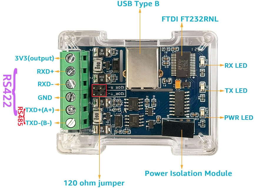
Pin Configuration and Descriptions
RS-485 Terminal Block Pinout
| Pin Name | Description |
|---|---|
| A (D+) | Non-inverting RS-485 data line |
| B (D-) | Inverting RS-485 data line |
| GND | Ground connection for RS-485 devices |
USB Connector Pinout (Type-A)
| Pin Name | Description |
|---|---|
| VBUS | +5V power supply from USB |
| D+ | USB data line (positive) |
| D- | USB data line (negative) |
| GND | Ground connection |
Usage Instructions
How to Use the RS-485-USB Converter in a Circuit
Connect the RS-485 Device:
- Connect the RS-485 device's
A (D+)andB (D-)lines to the corresponding terminals on the RS-485-USB converter. - Ensure the ground (
GND) of the RS-485 device is connected to the converter'sGND.
- Connect the RS-485 device's
Connect to a Computer:
- Plug the USB connector of the RS-485-USB converter into an available USB port on your computer.
Install Drivers (if required):
- Download and install the appropriate drivers for your operating system from the manufacturer's website.
Configure Communication Settings:
- Open a serial communication software (e.g., PuTTY, Tera Term, or a custom application).
- Select the correct COM port assigned to the RS-485-USB converter.
- Configure the baud rate, parity, stop bits, and data bits to match the RS-485 device's settings.
Test Communication:
- Send and receive data between the computer and the RS-485 device to verify proper operation.
Important Considerations and Best Practices
- Termination Resistor: If the RS-485 bus is long or has multiple devices, use a 120-ohm termination resistor at both ends of the bus to prevent signal reflections.
- Grounding: Ensure all devices on the RS-485 bus share a common ground to avoid communication errors.
- Cable Length: RS-485 supports cable lengths up to 1200 meters, but ensure the cable is shielded and twisted pair for optimal performance.
- Half-Duplex Communication: RS-485 is a half-duplex protocol, so ensure proper timing and direction control when sending and receiving data.
Example Code for Arduino UNO
If you are using the RS-485-USB converter with an Arduino UNO, you can use the following example code to send data to the computer:
#include <SoftwareSerial.h>

// Define RS-485 communication pins
#define RX_PIN 10  // Arduino pin connected to RS-485 RO (Receive Out)
#define TX_PIN 11  // Arduino pin connected to RS-485 DI (Data In)
#define DE_PIN 9   // Arduino pin connected to RS-485 DE (Driver Enable)

SoftwareSerial rs485Serial(RX_PIN, TX_PIN);

void setup() {
  pinMode(DE_PIN, OUTPUT);  // Set DE pin as output
  digitalWrite(DE_PIN, LOW); // Set DE to LOW for receiving initially
  rs485Serial.begin(9600);  // Initialize RS-485 communication at 9600 baud
  Serial.begin(9600);       // Initialize USB serial communication
}

void loop() {
  // Send data from Arduino to RS-485
  digitalWrite(DE_PIN, HIGH); // Enable RS-485 driver for sending
  rs485Serial.println("Hello from Arduino!");
  digitalWrite(DE_PIN, LOW);  // Disable RS-485 driver for receiving

  // Wait for a response from RS-485 device
  if (rs485Serial.available()) {
    String receivedData = rs485Serial.readString();
    Serial.println("Received: " + receivedData); // Print received data to USB
  }

  delay(1000); // Wait 1 second before sending again
}
Troubleshooting and FAQs
Common Issues and Solutions
No Communication Between Devices:
- Verify that the RS-485 device's
A (D+)andB (D-)lines are correctly connected to the converter. - Check that the baud rate and other communication settings match between the devices.
- Verify that the RS-485 device's
Driver Not Recognized:
- Ensure the correct driver is installed for your operating system.
- Try using a different USB port or cable.
Data Corruption or Noise:
- Use a shielded twisted-pair cable for RS-485 connections.
- Add termination resistors (120 ohms) at both ends of the RS-485 bus.
Converter Not Detected by Computer:
- Check if the USB port is functioning properly.
- Ensure the converter is securely connected to the USB port.
FAQs
Q: Can I use the RS-485-USB converter with multiple RS-485 devices?
A: Yes, RS-485 supports multi-drop communication. Ensure all devices share the same ground and use proper termination resistors.
Q: What is the maximum baud rate supported by the converter?
A: The RS-485-USB converter supports baud rates up to 3 Mbps, but ensure your RS-485 device and software can handle the selected baud rate.
Q: Do I need external power for the RS-485-USB converter?
A: No, the converter is powered directly from the USB port.
Q: Can I use this converter with macOS or Linux?
A: Yes, the converter is compatible with macOS and Linux, but you may need to install drivers depending on the chipset used.