Cirkit Designer Logo
Cirkit Designer
Your all-in-one circuit design IDE
Home / 
Component Documentation

How to Use Adafruit i2s 3w amp: Examples, Pinouts, and Specs

Image of Adafruit i2s 3w amp
Cirkit Designer LogoDesign with Adafruit i2s 3w amp in Cirkit Designer

Introduction

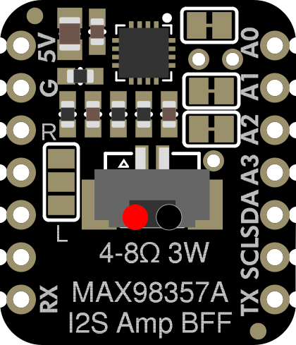
The Adafruit I2S 3W Amp is a compact and efficient audio amplifier designed to deliver high-quality sound output. It utilizes I2S (Inter-IC Sound) digital audio input, ensuring minimal noise and distortion while driving speakers with up to 3 watts of power. This amplifier is ideal for projects requiring clear audio playback in a small form factor.

Explore Projects Built with Adafruit i2s 3w amp

Use Cirkit Designer to design, explore, and prototype these projects online. Some projects support real-time simulation. Click "Open Project" to start designing instantly!
ESP32-Powered Smart Audio System with Data Logging
Image of Para Smart Speaker 1 Pro: A project utilizing Adafruit i2s 3w amp in a practical application
This circuit is a sophisticated audio playback and recording system with timekeeping functionality. It features an ESP32 S3 microcontroller for digital signal processing, connected to a DAC, an I2S microphone, an RTC, and a Micro SD card module. The audio output is handled by a 2.1 channel amplifier driving stereo speakers and a subwoofer, with power supplied by a series of 3.7V batteries and regulated by a DC step-down converter.
Cirkit Designer LogoOpen Project in Cirkit Designer
ESP32-C3 Mini and MCP4725 DAC Controlled Analog Output Circuit
Image of pp: A project utilizing Adafruit i2s 3w amp in a practical application
This circuit features an ESP32-C3 Mini microcontroller that interfaces with an Adafruit MCP4725 DAC via I2C for analog output, which is then fed into an OPA2333 operational amplifier. Power management is handled by a 5V step-down voltage regulator that receives power from a 2000mAh battery and supplies the ESP32-C3 and a 3.3V AMS1117 voltage regulator. Additionally, the circuit includes user input through buttons and electro pads, with debouncing provided by resistors.
Cirkit Designer LogoOpen Project in Cirkit Designer
Dual-Microcontroller Audio Processing System with Visual Indicators and Battery Management
Image of proto thesis 2: A project utilizing Adafruit i2s 3w amp in a practical application
This is a portable audio-visual device featuring two Wemos microcontrollers for processing, Adafruit MAX4466 microphone amplifiers for audio input, and an LCD TFT screen for display. It includes power management with TP4056 modules and LiPo batteries, and user-controlled toggle and rocker switches.
Cirkit Designer LogoOpen Project in Cirkit Designer
Voice-Activated ESP32 & Wemos Controllers with TFT Display and Battery Management
Image of prototype schematic: A project utilizing Adafruit i2s 3w amp in a practical application
This circuit features multiple microcontroller units (MCUs) including a Wemos S2 Mini, Wemos D1 Mini, and an ESP32 Devkit V1, each interfaced with an Adafruit MAX4466 Electret Microphone Amplifier for audio input and an LCD TFT screen for display output. The circuit is powered by Polymer Lithium Ion Batteries connected through TP4056 charging modules, with power management facilitated by push and rocker switches. The primary function of this circuit appears to be audio capture and processing with visual feedback.
Cirkit Designer LogoOpen Project in Cirkit Designer

Explore Projects Built with Adafruit i2s 3w amp

Use Cirkit Designer to design, explore, and prototype these projects online. Some projects support real-time simulation. Click "Open Project" to start designing instantly!
Image of Para Smart Speaker 1 Pro: A project utilizing Adafruit i2s 3w amp in a practical application
ESP32-Powered Smart Audio System with Data Logging
This circuit is a sophisticated audio playback and recording system with timekeeping functionality. It features an ESP32 S3 microcontroller for digital signal processing, connected to a DAC, an I2S microphone, an RTC, and a Micro SD card module. The audio output is handled by a 2.1 channel amplifier driving stereo speakers and a subwoofer, with power supplied by a series of 3.7V batteries and regulated by a DC step-down converter.
Cirkit Designer LogoOpen Project in Cirkit Designer
Image of pp: A project utilizing Adafruit i2s 3w amp in a practical application
ESP32-C3 Mini and MCP4725 DAC Controlled Analog Output Circuit
This circuit features an ESP32-C3 Mini microcontroller that interfaces with an Adafruit MCP4725 DAC via I2C for analog output, which is then fed into an OPA2333 operational amplifier. Power management is handled by a 5V step-down voltage regulator that receives power from a 2000mAh battery and supplies the ESP32-C3 and a 3.3V AMS1117 voltage regulator. Additionally, the circuit includes user input through buttons and electro pads, with debouncing provided by resistors.
Cirkit Designer LogoOpen Project in Cirkit Designer
Image of proto thesis 2: A project utilizing Adafruit i2s 3w amp in a practical application
Dual-Microcontroller Audio Processing System with Visual Indicators and Battery Management
This is a portable audio-visual device featuring two Wemos microcontrollers for processing, Adafruit MAX4466 microphone amplifiers for audio input, and an LCD TFT screen for display. It includes power management with TP4056 modules and LiPo batteries, and user-controlled toggle and rocker switches.
Cirkit Designer LogoOpen Project in Cirkit Designer
Image of prototype schematic: A project utilizing Adafruit i2s 3w amp in a practical application
Voice-Activated ESP32 & Wemos Controllers with TFT Display and Battery Management
This circuit features multiple microcontroller units (MCUs) including a Wemos S2 Mini, Wemos D1 Mini, and an ESP32 Devkit V1, each interfaced with an Adafruit MAX4466 Electret Microphone Amplifier for audio input and an LCD TFT screen for display output. The circuit is powered by Polymer Lithium Ion Batteries connected through TP4056 charging modules, with power management facilitated by push and rocker switches. The primary function of this circuit appears to be audio capture and processing with visual feedback.
Cirkit Designer LogoOpen Project in Cirkit Designer

Common Applications and Use Cases

  • Portable audio devices
  • DIY Bluetooth speakers
  • Voice assistants and smart home devices
  • Embedded systems requiring audio output
  • Educational and hobbyist electronics projects

Technical Specifications

Below are the key technical details of the Adafruit I2S 3W Amp:

Parameter Value
Input Type I2S Digital Audio
Output Power Up to 3W (at 4Ω, 10% THD)
Operating Voltage 3.3V to 5V
Speaker Impedance 4Ω to 8Ω
Frequency Response 20 Hz to 20 kHz
Dimensions 20mm x 20mm x 3mm

Pin Configuration and Descriptions

The Adafruit I2S 3W Amp has the following pin layout:

Pin Name Description
VIN Power input (3.3V to 5V). Connect to your power source.
GND Ground. Connect to the ground of your circuit.
DIN I2S Data Input. Connect to the data output pin of your microcontroller.
BCLK I2S Bit Clock. Connect to the bit clock pin of your microcontroller.
LRCLK I2S Left/Right Clock. Connect to the LR clock pin of your microcontroller.
+ Positive speaker terminal. Connect to the positive terminal of your speaker.
- Negative speaker terminal. Connect to the negative terminal of your speaker.

Usage Instructions

How to Use the Component in a Circuit

  1. Power the Amplifier: Connect the VIN pin to a 3.3V or 5V power source and the GND pin to ground.
  2. Connect the Speaker: Attach the positive and negative terminals of your speaker to the + and - pins of the amplifier, respectively.
  3. Connect I2S Signals:
    • Connect the DIN pin to the I2S data output pin of your microcontroller.
    • Connect the BCLK pin to the I2S bit clock pin of your microcontroller.
    • Connect the LRCLK pin to the I2S left/right clock pin of your microcontroller.
  4. Configure the Microcontroller: Ensure your microcontroller is configured to output I2S audio signals. Refer to the microcontroller's datasheet or documentation for I2S setup instructions.

Important Considerations and Best Practices

  • Use a speaker with an impedance of 4Ω to 8Ω for optimal performance.
  • Ensure the power supply voltage is within the specified range (3.3V to 5V) to avoid damaging the amplifier.
  • Keep the I2S signal wires as short as possible to minimize noise and signal degradation.
  • Avoid connecting the amplifier to speakers with power ratings significantly lower than 3W to prevent damage to the speaker.

Example: Connecting to an Arduino UNO

The Arduino UNO does not natively support I2S, but you can use an external I2S-compatible microcontroller (e.g., ESP32) to interface with the Adafruit I2S 3W Amp. Below is an example code snippet for an ESP32:

#include <Arduino.h>
#include <I2S.h>

// I2S configuration
#define I2S_BCLK 26  // Bit clock pin
#define I2S_LRCLK 25 // Left/Right clock pin
#define I2S_DOUT 22  // Data output pin

void setup() {
  // Initialize serial communication for debugging
  Serial.begin(115200);
  
  // Configure I2S with the specified pins
  if (!I2S.begin(I2S_PHILIPS_MODE, 44100, 16)) {
    Serial.println("Failed to initialize I2S!");
    while (1); // Halt execution if I2S initialization fails
  }
  I2S.setPins(I2S_BCLK, I2S_LRCLK, I2S_DOUT);
  Serial.println("I2S initialized successfully.");
}

void loop() {
  // Example: Generate a simple sine wave for testing
  static float phase = 0.0;
  const float frequency = 440.0; // Frequency of the sine wave (A4 note)
  const float amplitude = 32767.0; // Maximum amplitude for 16-bit audio
  const float sampleRate = 44100.0; // Sample rate in Hz

  // Calculate the next sample value
  int16_t sample = (int16_t)(amplitude * sin(phase));
  phase += 2.0 * PI * frequency / sampleRate;
  if (phase >= 2.0 * PI) phase -= 2.0 * PI;

  // Write the sample to the I2S output
  I2S.write(sample);
}

Notes:

  • Replace the pin numbers in the code with the actual GPIO pins used in your setup.
  • Ensure the speaker is connected properly before running the code.

Troubleshooting and FAQs

Common Issues and Solutions

  1. No Sound Output:

    • Verify that the I2S connections (DIN, BCLK, LRCLK) are correct and match the microcontroller's pin configuration.
    • Ensure the microcontroller is outputting valid I2S audio signals.
    • Check the power supply voltage and ensure it is within the specified range (3.3V to 5V).
  2. Distorted Audio:

    • Ensure the speaker impedance is within the recommended range (4Ω to 8Ω).
    • Reduce the audio signal volume if distortion occurs at high levels.
  3. Overheating:

    • Check for short circuits in the speaker connections.
    • Ensure the amplifier is not driving a speaker with an impedance lower than 4Ω.

FAQs

Q: Can I use this amplifier with a 3.3V microcontroller?
A: Yes, the Adafruit I2S 3W Amp is compatible with 3.3V and 5V systems.

Q: What is the maximum speaker power rating I can use?
A: You can use speakers rated for 3W or higher. Avoid using speakers with lower power ratings to prevent damage.

Q: Does the amplifier support stereo output?
A: No, the Adafruit I2S 3W Amp is a mono amplifier and supports a single speaker output.

Q: Can I use this amplifier with a Raspberry Pi?
A: Yes, the Raspberry Pi supports I2S and can be used to interface with the Adafruit I2S 3W Amp.