
How to Use QRE1113: Examples, Pinouts, and Specs
 Design with QRE1113 in Cirkit Designer
Introduction
The QRE1113 is an infrared emitter and phototransistor pair designed for proximity sensing and object detection. It operates by emitting infrared light and detecting the reflected light from nearby objects. This compact and efficient sensor is widely used in robotics and automation systems, particularly in applications such as line-following robots, obstacle detection, and edge detection.
Explore Projects Built with QRE1113
 Open Project in Cirkit Designer
 Open Project in Cirkit Designer
 Open Project in Cirkit Designer
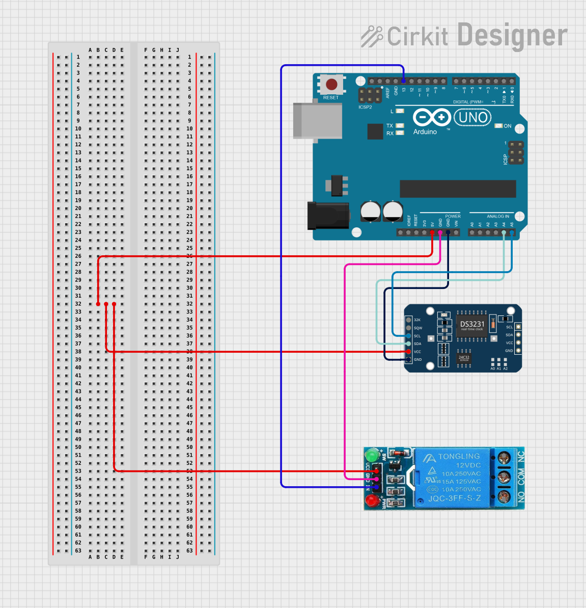 Open Project in Cirkit Designer
Explore Projects Built with QRE1113
Open Project in Cirkit DesignerOpen Project in Cirkit DesignerOpen Project in Cirkit DesignerOpen Project in Cirkit DesignerCommon Applications:
- Line-following robots
- Obstacle detection in robotics
- Edge detection in conveyor systems
- Reflective object sensing
- Position and motion detection
Technical Specifications
The QRE1113 is a reflective optical sensor with the following key specifications:
| Parameter | Value |
|---|---|
| Operating Voltage (Vcc) | 1.7V to 5.5V |
| Forward Current (Emitter) | 20 mA (typical) |
| Collector Current (Detector) | 1 mA (typical) |
| Peak Wavelength | 940 nm |
| Detection Range | 0.2 mm to 3 mm |
| Operating Temperature | -40°C to +85°C |
| Package Type | Surface Mount (SMD) |
Pin Configuration and Descriptions
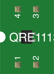
The QRE1113 has four pins, as described in the table below:
| Pin Number | Pin Name | Description |
|---|---|---|
| 1 | Emitter (+) | Positive terminal of the infrared LED (anode). |
| 2 | Emitter (-) | Negative terminal of the infrared LED (cathode). |
| 3 | Collector | Output of the phototransistor (collector terminal). |
| 4 | Emitter | Ground connection for the phototransistor. |
Usage Instructions
How to Use the QRE1113 in a Circuit
- Power Supply: Connect the infrared emitter (pins 1 and 2) to a suitable power source. Typically, a current-limiting resistor is used in series with the emitter to prevent excessive current. For example, with a 5V supply, use a resistor of approximately 220Ω.
- Phototransistor Output: Connect the phototransistor's collector (pin 3) to a pull-up resistor and then to the power supply. The emitter (pin 4) should be connected to ground. The output voltage at the collector will vary based on the amount of reflected infrared light detected.
- Placement: Position the QRE1113 close to the surface or object to be detected. The optimal detection range is between 0.2 mm and 3 mm.
- Signal Processing: The output signal from the phototransistor can be fed into a microcontroller's analog or digital input pin for further processing.
Important Considerations and Best Practices
- Ambient Light: Minimize ambient light interference by shielding the sensor or using it in controlled lighting conditions.
- Surface Reflectivity: The sensor's performance depends on the reflectivity of the surface. Highly reflective surfaces yield stronger signals.
- Current Limiting: Always use a current-limiting resistor with the infrared emitter to prevent damage.
- Distance Calibration: Calibrate the sensor for the specific distance and surface reflectivity of your application.
Example: Using QRE1113 with Arduino UNO
Below is an example of how to connect and use the QRE1113 with an Arduino UNO for line-following applications:
Circuit Connections:
- Connect pin 1 (Emitter +) to a 5V supply through a 220Ω resistor.
- Connect pin 2 (Emitter -) to ground.
- Connect pin 3 (Collector) to an Arduino analog input pin (e.g., A0) with a 10kΩ pull-up resistor to 5V.
- Connect pin 4 (Emitter) to ground.
Arduino Code:
// QRE1113 Line Sensor Example with Arduino UNO
// Reads the sensor output and prints the value to the Serial Monitor.

const int sensorPin = A0; // Analog pin connected to QRE1113 collector

void setup() {
  Serial.begin(9600); // Initialize serial communication at 9600 baud
}

void loop() {
  int sensorValue = analogRead(sensorPin); // Read the analog value from the sensor
  Serial.print("Sensor Value: ");
  Serial.println(sensorValue); // Print the sensor value to the Serial Monitor

  delay(100); // Small delay for stability
}
Notes:
- The
sensorValuewill be lower when the sensor detects a reflective surface (e.g., white) and higher for non-reflective surfaces (e.g., black). - Adjust the pull-up resistor value if the output signal is too weak or noisy.
Troubleshooting and FAQs
Common Issues and Solutions
No Output Signal:
- Cause: Incorrect wiring or missing pull-up resistor.
- Solution: Double-check the connections and ensure a pull-up resistor is connected to the phototransistor's collector.
Weak or No Detection:
- Cause: The object is outside the sensor's detection range or has low reflectivity.
- Solution: Ensure the object is within 0.2 mm to 3 mm of the sensor and has a reflective surface.
Inconsistent Readings:
- Cause: Ambient light interference or unstable power supply.
- Solution: Shield the sensor from ambient light and use a stable power source.
Overheating:
- Cause: Excessive current through the infrared emitter.
- Solution: Use an appropriate current-limiting resistor for the emitter.
FAQs
Q1: Can the QRE1113 detect transparent objects?
A1: No, the QRE1113 is not suitable for detecting transparent objects as they do not reflect sufficient infrared light.
Q2: What is the maximum detection distance?
A2: The QRE1113 can detect objects up to 3 mm away, depending on the surface reflectivity.
Q3: Can I use the QRE1113 with a 3.3V system?
A3: Yes, the QRE1113 operates within a voltage range of 1.7V to 5.5V, making it compatible with 3.3V systems.
Q4: How do I improve detection accuracy?
A4: Use the sensor in a controlled environment with minimal ambient light and ensure proper alignment with the target surface.
By following this documentation, you can effectively integrate the QRE1113 into your projects for reliable proximity sensing and object detection.