How to Use Amplifier: Examples, Pinouts, and Specs
Introduction
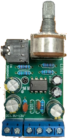
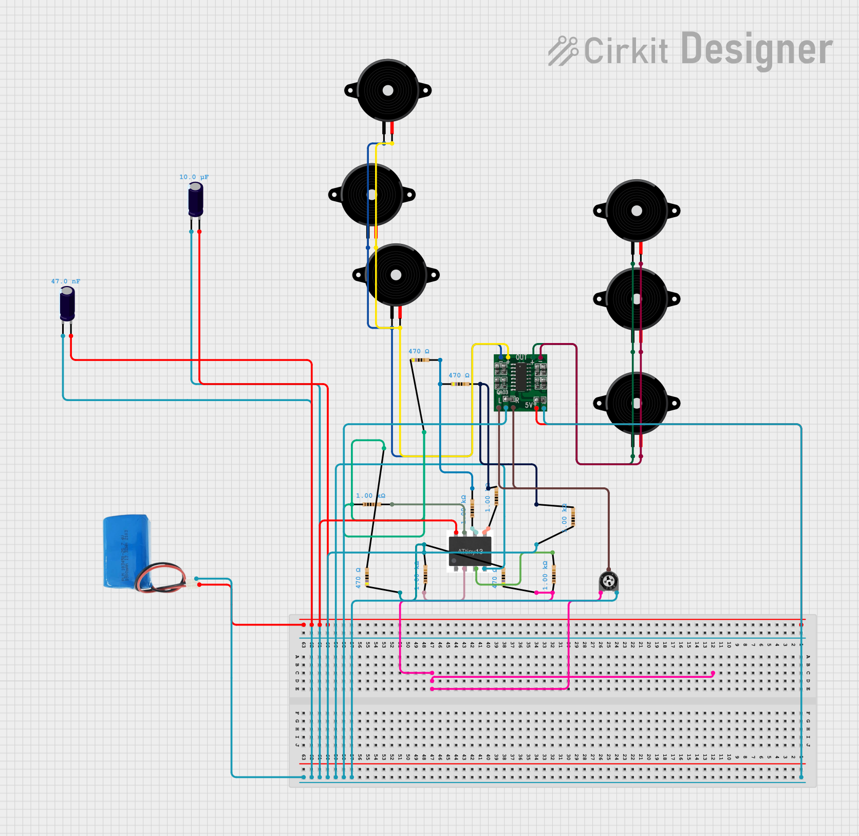
The TDA2822M is a low-power audio amplifier manufactured by DAOKI. It is a dual-channel (stereo) amplifier designed for use in portable audio devices, radios, and other low-power audio applications. This component is ideal for battery-powered devices due to its low power consumption and ability to operate at low voltages. The TDA2822M is compact, reliable, and easy to integrate into various audio circuits.
Explore Projects Built with Amplifier
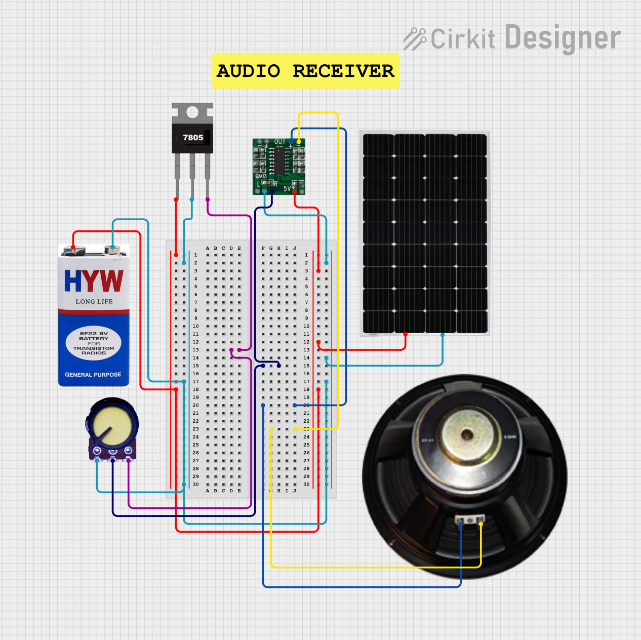
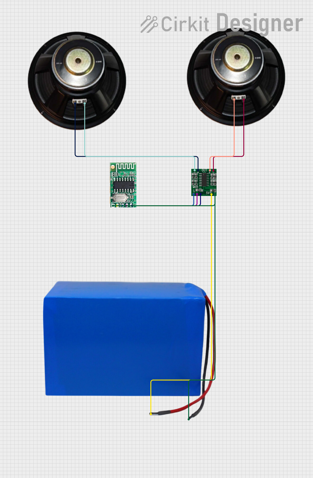
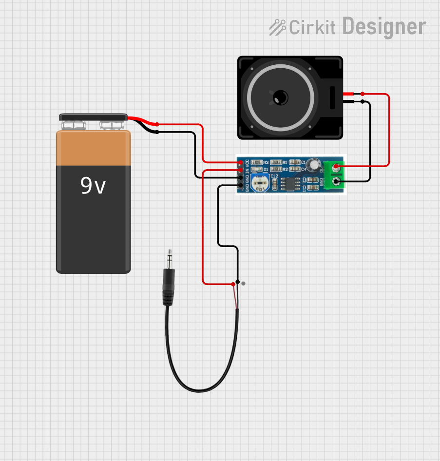
Explore Projects Built with Amplifier
Common Applications
- Portable audio devices (e.g., MP3 players, radios)
- Headphone amplifiers
- Intercom systems
- Low-power speaker systems
- DIY audio projects
Technical Specifications
The TDA2822M is a versatile amplifier with the following key specifications:
| Parameter | Value |
|---|---|
| Supply Voltage (Vcc) | 1.8V to 15V |
| Output Power | 1W per channel (at 8Ω, Vcc = 6V) |
| Quiescent Current | 6mA (typical) |
| Gain | 39 dB |
| Total Harmonic Distortion | 0.2% (at 1kHz, Pout = 250mW) |
| Input Impedance | 100kΩ |
| Operating Temperature | -40°C to +85°C |
| Package Type | 8-pin DIP or SOP |
Pin Configuration
The TDA2822M comes in an 8-pin package. Below is the pinout and description:
| Pin Number | Pin Name | Description |
|---|---|---|
| 1 | OUT1 | Output for Channel 1 |
| 2 | Vcc | Positive power supply |
| 3 | IN1(-) | Inverting input for Channel 1 |
| 4 | IN2(-) | Inverting input for Channel 2 |
| 5 | GND | Ground |
| 6 | IN2(+) | Non-inverting input for Channel 2 |
| 7 | IN1(+) | Non-inverting input for Channel 1 |
| 8 | OUT2 | Output for Channel 2 |
Usage Instructions
How to Use the TDA2822M in a Circuit
- Power Supply: Connect the Vcc pin (Pin 2) to a DC power source within the range of 1.8V to 15V. Connect the GND pin (Pin 5) to the ground of the circuit.
- Input Signal: Feed the audio signal to the non-inverting inputs (Pins 6 and 7) for Channels 2 and 1, respectively. Optionally, connect the inverting inputs (Pins 3 and 4) to ground or use them for differential input configurations.
- Output Load: Connect the outputs (Pins 1 and 8) to the speakers or headphones. Ensure the load impedance matches the amplifier's specifications (typically 8Ω or higher).
- Decoupling Capacitors: Place a decoupling capacitor (e.g., 100µF) between the Vcc and GND pins to stabilize the power supply.
- Coupling Capacitors: Use coupling capacitors (e.g., 10µF) at the input and output to block DC components and allow only the AC audio signal to pass.
Example Circuit
Below is a basic stereo amplifier circuit using the TDA2822M:
       +Vcc
        |
       [C1] 100µF
        |
        +------------------+
        |                  |
       [R1] 10kΩ         [R2] 10kΩ
        |                  |
       IN1(+)            IN2(+)
        |                  |
       [C2] 10µF         [C3] 10µF
        |                  |
       GND                GND
Arduino Integration Example
The TDA2822M can be used with an Arduino UNO to amplify audio signals. Below is an example code snippet to generate a simple tone and send it to the amplifier:
// Arduino Example: Generate a tone for the TDA2822M amplifier
// Connect the amplifier's input to Arduino pin 9 (PWM output)

#define AUDIO_PIN 9  // PWM pin connected to the amplifier input

void setup() {
  pinMode(AUDIO_PIN, OUTPUT);  // Set the pin as output
}

void loop() {
  // Generate a 1kHz square wave
  tone(AUDIO_PIN, 1000);  // Play a 1kHz tone
  delay(1000);            // Play for 1 second
  noTone(AUDIO_PIN);      // Stop the tone
  delay(1000);            // Wait for 1 second
}
Important Considerations
- Heat Dissipation: Although the TDA2822M is a low-power amplifier, ensure proper ventilation or a small heatsink if operating at higher power levels.
- Speaker Impedance: Use speakers with an impedance of 8Ω or higher to avoid overloading the amplifier.
- Power Supply Noise: Use decoupling capacitors to minimize noise from the power supply.
Troubleshooting and FAQs
Common Issues
No Output Signal:
- Check the power supply voltage and ensure it is within the specified range.
- Verify all connections, especially the input and output pins.
- Ensure the input signal is present and properly connected.
Distorted Audio:
- Check the load impedance; it should match the amplifier's specifications.
- Ensure the input signal amplitude is not too high, as it may cause clipping.
- Verify the coupling capacitors are of the correct value and not damaged.
Excessive Heat:
- Ensure the amplifier is not overloaded by using speakers with the correct impedance.
- Check for short circuits in the output connections.
FAQs
Q: Can the TDA2822M be used in a mono configuration?
A: Yes, the TDA2822M can be configured as a mono amplifier by bridging the two channels. This increases the output power but requires careful design to avoid phase issues.
Q: What is the maximum output power of the TDA2822M?
A: The maximum output power is 1W per channel when driving an 8Ω load at a supply voltage of 6V.
Q: Can I use the TDA2822M with a 3.3V power supply?
A: Yes, the TDA2822M can operate with a supply voltage as low as 1.8V, making it suitable for 3.3V systems.
Q: How do I reduce noise in my circuit?
A: Use decoupling capacitors near the power supply pins and ensure proper grounding. Additionally, keep input signal wires short to minimize interference.
This concludes the documentation for the TDA2822M amplifier. For further assistance, refer to the manufacturer's datasheet or contact DAOKI support.