How to Use TB6560: Examples, Pinouts, and Specs
Introduction
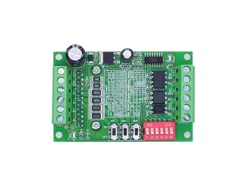
The TB6560 is a microstepping driver designed for bipolar stepper motors. It is capable of driving motors with a current rating of up to 3A per phase, making it suitable for a wide range of applications. The driver features adjustable current control, which ensures smooth motor operation and reduces noise. Additionally, it supports multiple microstepping resolutions, allowing for precise control of stepper motors. The TB6560 is widely used in CNC machines, 3D printers, robotics, and other motion control systems.
Explore Projects Built with TB6560


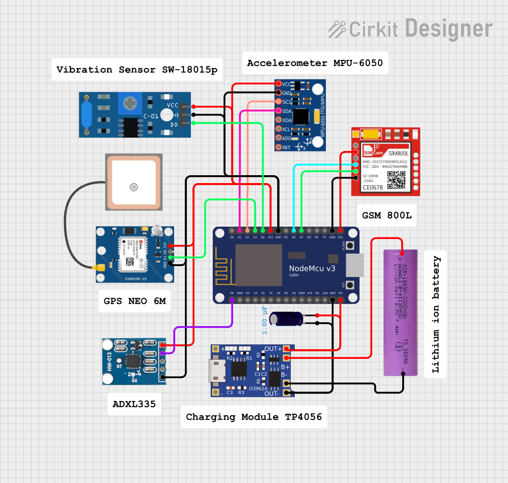
Explore Projects Built with TB6560
Technical Specifications
Below are the key technical details of the TB6560 stepper motor driver:
- Operating Voltage: 10V to 35V DC
- Maximum Output Current: 3A per phase (adjustable)
- Microstepping Modes: Full step, half step, 1/8 step, 1/16 step
- Control Signal Voltage: 3.3V or 5V logic compatible
- Input Signals: Step, Direction, Enable
- Overcurrent Protection: Yes
- Overheat Protection: Yes
- Decay Mode: Adjustable (fast, slow, or mixed decay)
- Dimensions: Varies by module, typically 75mm x 50mm x 35mm
Pin Configuration and Descriptions
The TB6560 driver module typically has the following pin configuration:
Input Signal Pins
| Pin Name | Description | Voltage Level |
|---|---|---|
EN |
Enable signal (active low) | 3.3V or 5V |
DIR |
Direction control signal | 3.3V or 5V |
PUL |
Step pulse signal | 3.3V or 5V |
Motor Output Pins
| Pin Name | Description |
|---|---|
A+ |
Positive terminal of coil A |
A- |
Negative terminal of coil A |
B+ |
Positive terminal of coil B |
B- |
Negative terminal of coil B |
Power Supply Pins
| Pin Name | Description | Voltage Level |
|---|---|---|
VCC |
Power supply input | 10V to 35V DC |
GND |
Ground | 0V |
Configuration Pins (DIP Switches or Jumpers)
| Setting | Description |
|---|---|
| Current Adjustment | Sets the maximum current limit for the motor |
| Microstepping Mode | Configures the microstepping resolution |
| Decay Mode | Adjusts the decay mode (fast, slow, or mixed) |
Usage Instructions
Connecting the TB6560 to a Stepper Motor
- Power Supply: Connect a DC power supply (10V to 35V) to the
VCCandGNDpins. Ensure the power supply can provide sufficient current for the motor. - Motor Connections: Connect the stepper motor's coils to the
A+,A-,B+, andB-terminals. Refer to the motor's datasheet to identify the correct coil pairs. - Control Signals: Connect the
PUL,DIR, andENpins to a microcontroller or control board. Ensure the logic voltage levels are compatible (3.3V or 5V). - Configuration: Use the DIP switches or jumpers to set the desired current limit, microstepping mode, and decay mode.
Example: Using the TB6560 with an Arduino UNO
Below is an example of how to control a stepper motor using the TB6560 and an Arduino UNO:
Circuit Connections
- Connect
PULto Arduino pin 2. - Connect
DIRto Arduino pin 3. - Connect
ENto Arduino pin 4. - Connect the stepper motor coils to the
A+,A-,B+, andB-terminals. - Connect a 12V DC power supply to the
VCCandGNDpins.
Arduino Code
// Define control pins
#define PUL_PIN 2  // Step pulse pin
#define DIR_PIN 3  // Direction pin
#define EN_PIN 4   // Enable pin

void setup() {
  // Set control pins as outputs
  pinMode(PUL_PIN, OUTPUT);
  pinMode(DIR_PIN, OUTPUT);
  pinMode(EN_PIN, OUTPUT);

  // Enable the driver (active low)
  digitalWrite(EN_PIN, LOW);

  // Set initial direction
  digitalWrite(DIR_PIN, HIGH);
}

void loop() {
  // Generate step pulses
  for (int i = 0; i < 200; i++) { // 200 steps for one revolution (1.8°/step)
    digitalWrite(PUL_PIN, HIGH); // Set pulse high
    delayMicroseconds(500);      // Pulse width (500µs)
    digitalWrite(PUL_PIN, LOW);  // Set pulse low
    delayMicroseconds(500);      // Delay between pulses
  }

  // Change direction
  digitalWrite(DIR_PIN, !digitalRead(DIR_PIN)); // Toggle direction
  delay(1000); // Wait 1 second before next revolution
}
Important Considerations
- Current Adjustment: Set the current limit to match the stepper motor's rated current to avoid overheating or damaging the motor.
- Cooling: The TB6560 driver may require a heatsink or active cooling (e.g., a fan) for high-current applications.
- Signal Timing: Ensure the step pulse width and delay meet the motor's requirements for smooth operation.
- Power Supply: Use a stable and adequately rated power supply to prevent voltage drops or fluctuations.
Troubleshooting and FAQs
Common Issues
Motor Not Moving:
- Check all connections, especially the motor coils and control signals.
- Verify that the
ENpin is set to LOW (enabled). - Ensure the power supply voltage is within the specified range.
Motor Vibrates but Does Not Rotate:
- Verify the coil connections. Incorrect wiring can cause the motor to vibrate without rotating.
- Check the microstepping settings and ensure they match the control signals.
Driver Overheating:
- Ensure the current limit is set correctly using the DIP switches.
- Add a heatsink or fan to improve cooling.
Inconsistent Motor Movement:
- Check the step pulse timing in the control code.
- Ensure the power supply is stable and not overloaded.
FAQs
Q: Can the TB6560 drive unipolar stepper motors?
A: No, the TB6560 is designed for bipolar stepper motors only.
Q: What is the maximum step pulse frequency?
A: The TB6560 can handle step pulse frequencies up to 200 kHz.
Q: How do I select the microstepping mode?
A: Use the DIP switches or jumpers on the driver module to configure the microstepping resolution. Refer to the module's datasheet for the specific settings.
Q: Can I use the TB6560 with a 24V power supply?
A: Yes, the TB6560 supports power supply voltages between 10V and 35V. Ensure the motor is compatible with the selected voltage.
By following this documentation, users can effectively integrate the TB6560 into their projects and troubleshoot common issues.