
How to Use V_REG_TPS61040: Examples, Pinouts, and Specs
 Design with V_REG_TPS61040 in Cirkit Designer
Introduction
The TPS61040 is a high-efficiency boost converter designed to step up low input voltages to higher output voltages. It is particularly well-suited for battery-powered applications, where efficient power conversion is critical. This component integrates a power switch and requires minimal external components, making it ideal for compact designs. Its adjustable output voltage and wide input voltage range make it versatile for a variety of applications.
Explore Projects Built with V_REG_TPS61040
 Open Project in Cirkit Designer
 Open Project in Cirkit Designer
 Open Project in Cirkit Designer
 Open Project in Cirkit Designer
Explore Projects Built with V_REG_TPS61040
Open Project in Cirkit DesignerOpen Project in Cirkit DesignerOpen Project in Cirkit DesignerOpen Project in Cirkit DesignerCommon Applications
- Portable electronics powered by single-cell or multi-cell batteries
- LED backlighting for displays
- Low-power industrial and medical devices
- Wireless communication modules
- Sensor systems requiring higher operating voltages
Technical Specifications
Key Specifications
| Parameter | Value |
|---|---|
| Input Voltage Range | 1.8 V to 6.0 V |
| Output Voltage Range | Adjustable, up to 28 V |
| Maximum Output Current | 400 mA (depending on input/output) |
| Switching Frequency | 1.2 MHz |
| Efficiency | Up to 90% |
| Quiescent Current | 28 µA |
| Shutdown Current | < 1 µA |
| Package Type | SOT-23-6 |
Pin Configuration and Descriptions
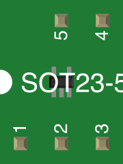
The TPS61040 is available in a 6-pin SOT-23 package. Below is the pinout and description:
| Pin Number | Pin Name | Description |
|---|---|---|
| 1 | SW | Switch pin. Connect to the inductor and diode. |
| 2 | GND | Ground pin. Connect to system ground. |
| 3 | FB | Feedback pin. Connect to a resistor divider to set the output voltage. |
| 4 | EN | Enable pin. High to enable the device, low to disable it. |
| 5 | VIN | Input voltage pin. Connect to the power source. |
| 6 | VOUT | Output voltage pin. Connect to the output capacitor and load. |
Usage Instructions
How to Use the TPS61040 in a Circuit
- Input Voltage: Ensure the input voltage is within the range of 1.8 V to 6.0 V.
- Output Voltage Setting: Use a resistor divider network connected to the FB pin to set the desired output voltage. The formula for the output voltage is: [ V_{OUT} = V_{REF} \times \left(1 + \frac{R1}{R2}\right) ] where ( V_{REF} ) is typically 1.233 V.
- Inductor Selection: Choose an inductor with a suitable inductance value (e.g., 4.7 µH to 22 µH) and current rating to handle the peak current.
- Capacitor Selection: Use low ESR capacitors for both input and output. Typical values are:
- Input capacitor: 4.7 µF to 10 µF
- Output capacitor: 10 µF to 22 µF
- Diode Selection: Use a fast-recovery Schottky diode with a voltage rating higher than the output voltage and a current rating exceeding the peak inductor current.
- Enable Pin: Connect the EN pin to VIN or a microcontroller GPIO to enable or disable the device.
Example Circuit
Below is a basic circuit diagram for the TPS61040:
VIN ----+----+----+
        |    |    |
       C1   L1   D1
        |    |    |
       GND  SW   VOUT
             |     |
            FB    C2
             |     |
            R1    GND
             |
            R2
             |
            GND
Arduino UNO Example Code
The TPS61040 can be controlled using an Arduino UNO to enable or disable the boost converter. Below is an example code snippet:
// Define the pin connected to the EN pin of TPS61040
const int enablePin = 7;

void setup() {
  // Set the enable pin as an output
  pinMode(enablePin, OUTPUT);

  // Enable the TPS61040 by setting the pin HIGH
  digitalWrite(enablePin, HIGH);
}

void loop() {
  // Keep the TPS61040 enabled
  delay(1000);

  // Example: Disable the TPS61040 for 2 seconds
  digitalWrite(enablePin, LOW);
  delay(2000);

  // Re-enable the TPS61040
  digitalWrite(enablePin, HIGH);
}
Important Considerations
- Thermal Management: Ensure adequate heat dissipation, especially at high output currents.
- PCB Layout: Minimize the trace lengths for the SW pin and the ground connections to reduce noise and improve efficiency.
- Startup Behavior: The device may require a minimum input voltage to start up, depending on the load.
Troubleshooting and FAQs
Common Issues and Solutions
No Output Voltage:
- Verify that the EN pin is pulled high.
- Check the input voltage to ensure it is within the specified range.
- Inspect the feedback resistor network for proper connections and values.
Low Efficiency:
- Ensure the inductor and capacitors have low ESR and are appropriately rated.
- Minimize PCB trace resistance and ensure proper grounding.
Output Voltage Instability:
- Verify the feedback resistor values and connections.
- Check the output capacitor for sufficient capacitance and low ESR.
Device Overheating:
- Ensure the load current does not exceed the maximum rating.
- Improve thermal dissipation by using a larger copper area on the PCB.
FAQs
Q1: Can the TPS61040 operate with a single AA battery?
A1: Yes, the TPS61040 can operate with a single AA battery (1.8 V to 6.0 V input range), but the output current capability will depend on the input voltage and desired output voltage.
Q2: How do I calculate the inductor value?
A2: The inductor value depends on the input voltage, output voltage, and switching frequency. A typical range is 4.7 µH to 22 µH. Refer to the datasheet for detailed calculations.
Q3: Can I use the TPS61040 to power LEDs?
A3: Yes, the TPS61040 is suitable for driving LEDs. Use a current-limiting resistor or a constant-current circuit to protect the LEDs.
Q4: What happens if the EN pin is left floating?
A4: The EN pin should not be left floating. Connect it to VIN or a GPIO pin to ensure proper operation.