
How to Use 7-Segment Panel Voltmeter: Examples, Pinouts, and Specs
 Design with 7-Segment Panel Voltmeter in Cirkit Designer
Introduction
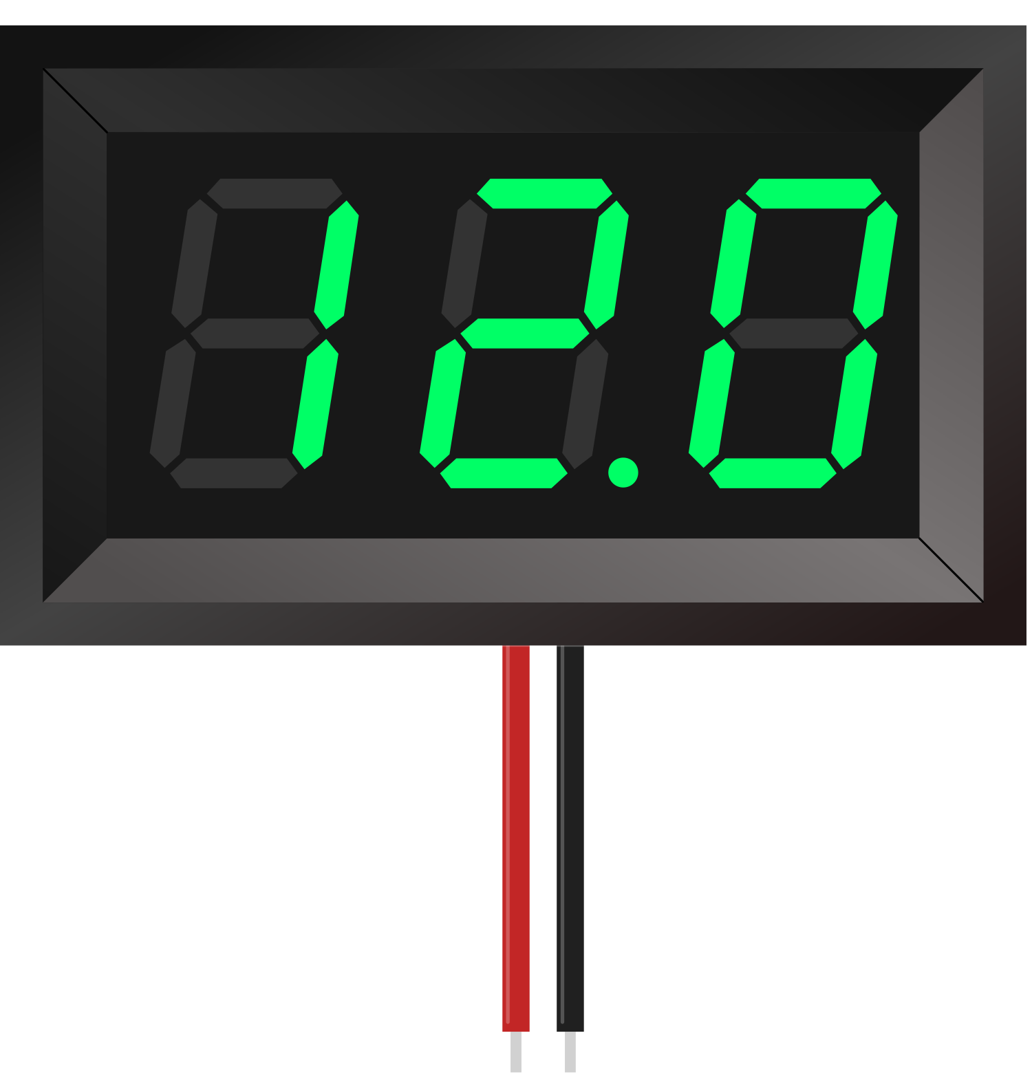
A 7-segment panel voltmeter is an electronic device used to measure and display voltage levels in a circuit. It features a digital display made up of seven segments that can be illuminated to represent numerical values, providing a clear and easy-to-read output of the measured voltage.
This component is commonly used in power supplies, battery monitoring systems, and other electronic projects where real-time voltage monitoring is essential. Its compact design and straightforward interface make it a popular choice for both hobbyists and professionals.
Explore Projects Built with 7-Segment Panel Voltmeter
 Open Project in Cirkit Designer
 Open Project in Cirkit Designer
 Open Project in Cirkit Designer
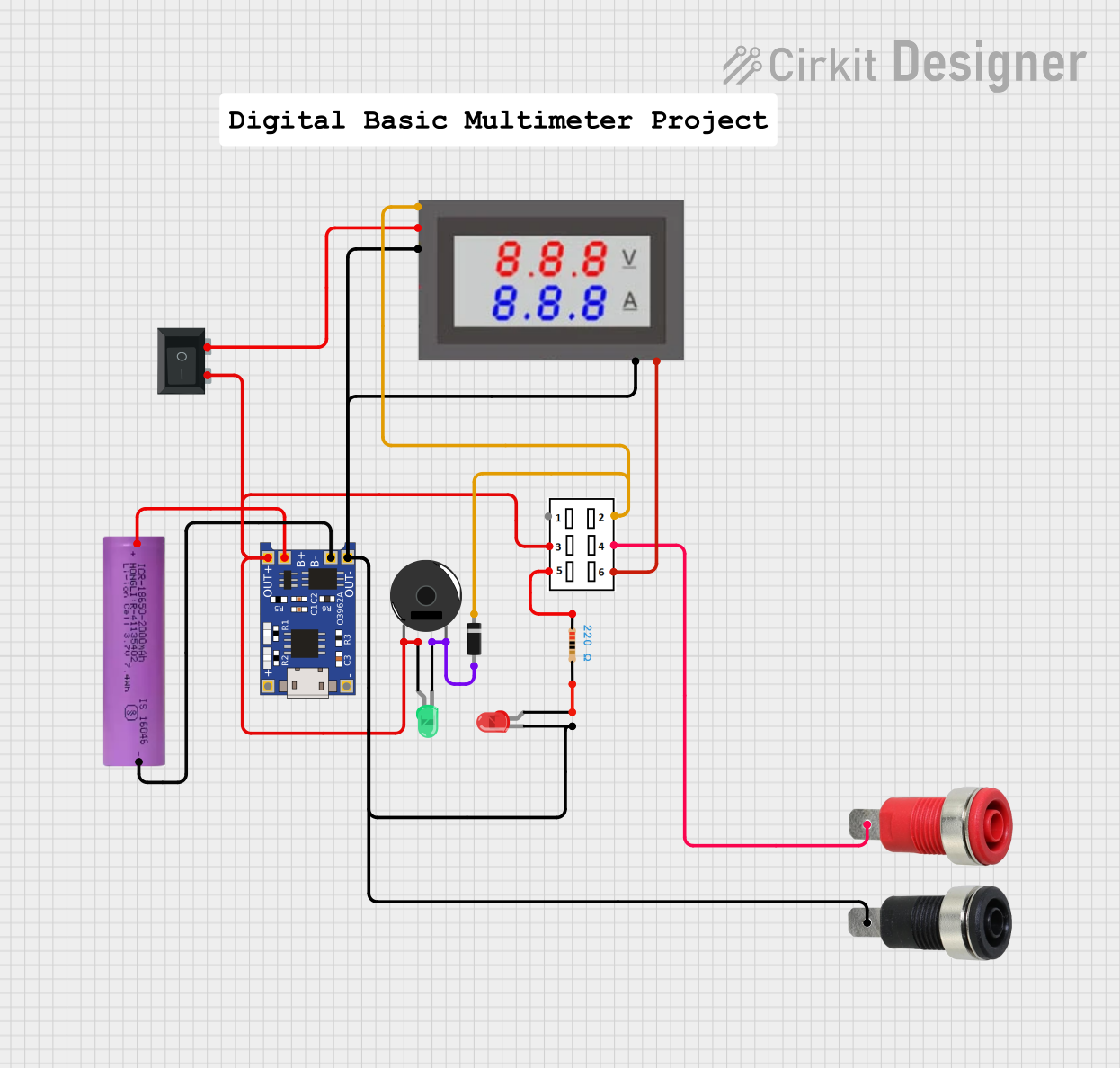 Open Project in Cirkit Designer
Explore Projects Built with 7-Segment Panel Voltmeter
Open Project in Cirkit DesignerOpen Project in Cirkit DesignerOpen Project in Cirkit DesignerOpen Project in Cirkit DesignerTechnical Specifications
- Input Voltage Range: Typically 0V to 100V DC (varies by model)
- Operating Voltage: 3.3V to 30V DC (for powering the module)
- Display Type: 7-segment LED display
- Display Color: Red, Green, or Blue (depending on the model)
- Accuracy: ±1% (varies by manufacturer)
- Refresh Rate: ~200ms (5 times per second)
- Power Consumption: Low (typically <20mA)
- Dimensions: Compact, e.g., 48mm x 29mm x 21mm (varies by model)
Pin Configuration and Descriptions
The 7-segment panel voltmeter typically has three or four pins for connection. Below is a table describing the pin configuration:
| Pin | Label | Description |
|---|---|---|
| 1 | VCC | Power supply input (3.3V to 30V DC). Provides power to the voltmeter module. |
| 2 | GND | Ground connection. Common ground for power and measurement. |
| 3 | VIN | Voltage input to be measured. Connect this pin to the voltage source to monitor. |
| 4* | ADJ | (Optional) Adjustment pin for calibration. Used to fine-tune the displayed value. |
* Note: Not all models include the ADJ pin. Refer to the specific datasheet for your model.
Usage Instructions
How to Use the Component in a Circuit
- Power the Module: Connect the VCC pin to a DC power source (3.3V to 30V) and the GND pin to the ground of the power source.
- Connect the Voltage Source: Attach the VIN pin to the voltage source you want to measure. Ensure the voltage does not exceed the module's input range (e.g., 0V to 100V DC).
- Optional Calibration: If your module includes an ADJ pin, use a small screwdriver to adjust the potentiometer for precise calibration. Compare the displayed value with a known accurate multimeter for reference.
Important Considerations and Best Practices
- Voltage Range: Ensure the input voltage (VIN) does not exceed the specified range of the module to avoid damage.
- Power Supply: Use a stable DC power source to power the module. Avoid noisy or fluctuating power supplies.
- Polarity: Double-check the polarity of your connections. Reversing the VCC and GND connections can damage the module.
- Isolation: If measuring high voltages, consider using an isolation circuit to protect the voltmeter and other components in your system.
- Mounting: Secure the module in a panel or enclosure to protect it from physical damage and ensure clear visibility of the display.
Example: Connecting to an Arduino UNO
The 7-segment panel voltmeter can be used alongside an Arduino UNO to monitor voltage levels in a circuit. Below is an example of how to connect and use the voltmeter:
Circuit Connections
- Connect the VCC pin of the voltmeter to the 5V pin on the Arduino.
- Connect the GND pin of the voltmeter to the GND pin on the Arduino.
- Connect the VIN pin of the voltmeter to the voltage source you want to measure.
Arduino Code Example
Although the voltmeter operates independently, you can use the Arduino to measure the same voltage and compare the readings. Here's an example code snippet:
// Define the analog pin for voltage measurement
const int voltagePin = A0; // Connect the voltage source to A0

void setup() {
  Serial.begin(9600); // Initialize serial communication
}

void loop() {
  // Read the analog value (0-1023) from the voltage pin
  int sensorValue = analogRead(voltagePin);

  // Convert the analog value to voltage (assuming 5V reference)
  float voltage = sensorValue * (5.0 / 1023.0);

  // Print the voltage to the Serial Monitor
  Serial.print("Measured Voltage: ");
  Serial.print(voltage);
  Serial.println(" V");

  delay(500); // Wait for 500ms before the next reading
}
Note: The Arduino's analog input can only measure up to 5V directly. If you need to measure higher voltages, use a voltage divider circuit to step down the voltage.
Troubleshooting and FAQs
Common Issues
No Display or Flickering Display:
- Cause: Insufficient power supply or loose connections.
- Solution: Ensure the VCC pin is connected to a stable DC power source within the specified range. Check all connections for proper contact.
Incorrect Voltage Reading:
- Cause: Calibration error or noisy input signal.
- Solution: Use the ADJ pin (if available) to calibrate the display. Ensure the input voltage is stable and free from noise.
Display Does Not Turn On:
- Cause: Reversed polarity or damaged module.
- Solution: Verify the polarity of the VCC and GND connections. If the module is damaged, replace it.
FAQs
Q: Can this voltmeter measure AC voltage?
A: No, this module is designed for DC voltage measurement only. For AC voltage, use an appropriate AC voltmeter.Q: How do I measure voltages higher than the module's range?
A: Use a voltage divider circuit to step down the voltage to a measurable range. Ensure the divider ratio is accurate.Q: Can I use this module with a 12V battery?
A: Yes, the module can measure the voltage of a 12V battery as long as the input voltage is within the specified range.Q: Is the display brightness adjustable?
A: No, the brightness is fixed and depends on the module's design.
By following this documentation, you can effectively integrate and troubleshoot a 7-segment panel voltmeter in your projects.