How to Use Adafruit TFT 2.2 inch 320x240 w microSD: Examples, Pinouts, and Specs
Introduction
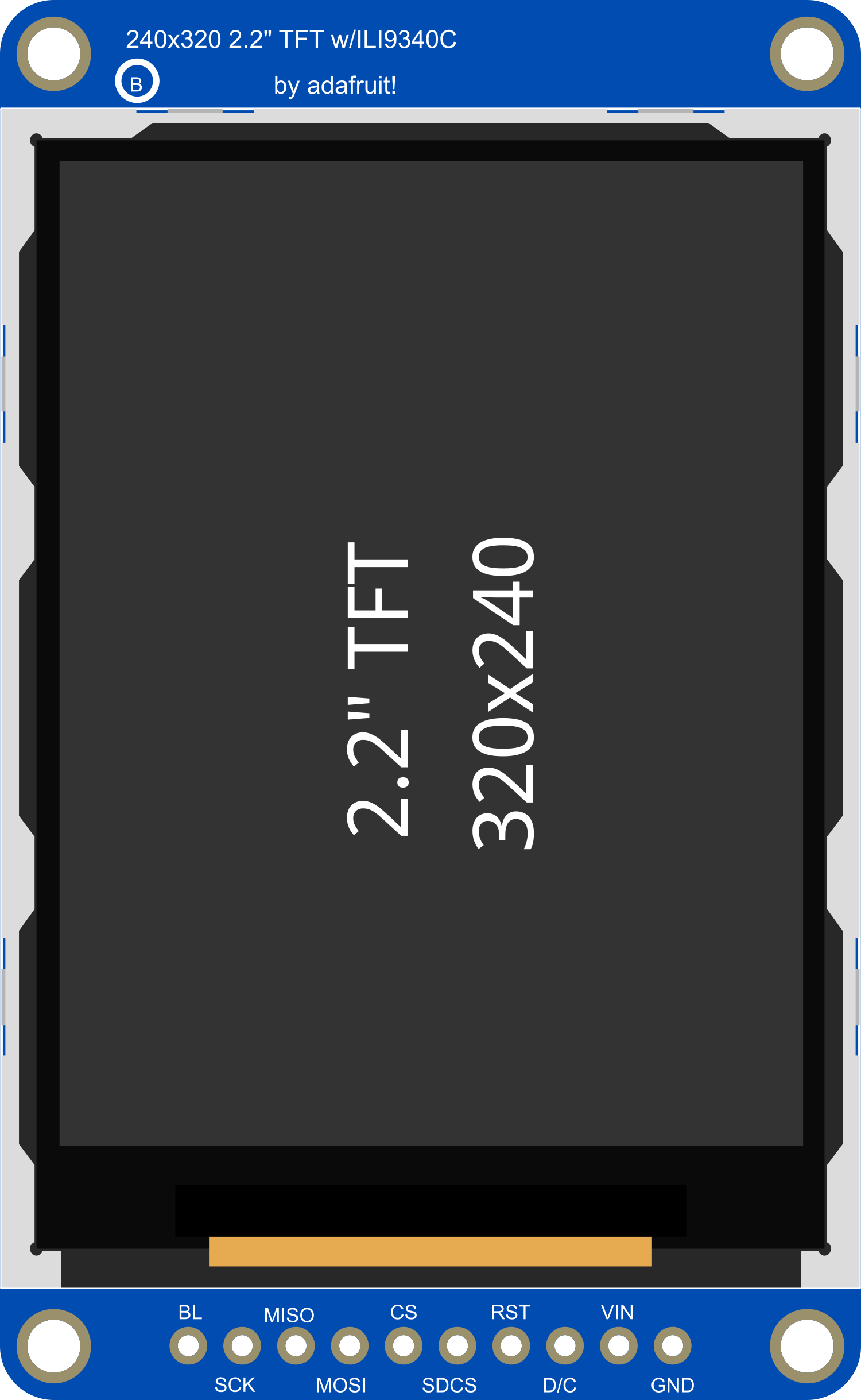
The Adafruit TFT 2.2 inch 320x240 Touchscreen with microSD is a versatile and compact display module that features a 2.2-inch TFT LCD screen, offering a resolution of 320x240 pixels. This module is equipped with a resistive touch panel, allowing for user input and interaction, and a microSD card slot, which can be used for storing images, text, and other data for display purposes. Common applications include handheld instruments, touch-based control panels, and embedded systems requiring a graphical user interface.
Explore Projects Built with Adafruit TFT 2.2 inch 320x240 w microSD


Explore Projects Built with Adafruit TFT 2.2 inch 320x240 w microSD
Technical Specifications
Display Characteristics
- Screen Size: 2.2 inches
- Resolution: 320x240 pixels
- Display Type: TFT LCD
- Interface: SPI
Touch Panel
- Type: Resistive touch panel
- Interface: Analog
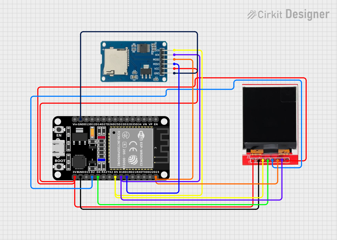
microSD Card Slot
- Supported Card Type: Standard microSD cards
Power Requirements
- Supply Voltage: 3.3V to 5V
- Logic Level: 3.3V (5V tolerant)
Pin Configuration
| Pin Number | Function | Description |
|---|---|---|
| 1 | VCC | Power supply (3.3V to 5V) |
| 2 | GND | Ground |
| 3 | CS | Chip Select for TFT |
| 4 | RESET | Reset pin |
| 5 | D/C | Data/Command control pin |
| 6 | MOSI | Master Out Slave In for SPI |
| 7 | SCK | Serial Clock for SPI |
| 8 | LED | Backlight control (optional PWM) |
| 9 | MISO | Master In Slave Out for SPI (optional) |
| 10 | T_CLK | Touch Clock (optional if sharing with SCK) |
| 11 | T_CS | Touch Chip Select |
| 12 | T_DIN | Touch Data In (optional if sharing MOSI) |
| 13 | T_DO | Touch Data Out (optional if sharing MISO) |
| 14 | T_IRQ | Touch Interrupt |
| 15 | SD_CS | microSD Chip Select |
Usage Instructions
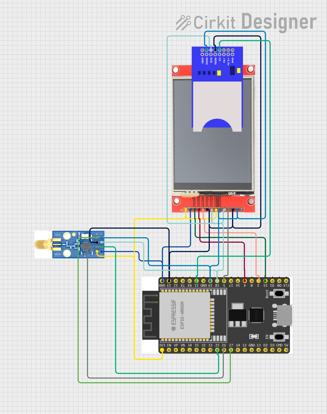
Wiring to an Arduino UNO
- Connect VCC to 5V on the Arduino.
- Connect GND to GND on the Arduino.
- Connect CS, RESET, D/C, MOSI, SCK, and LED to digital pins on the Arduino (e.g., pins 10, 9, 8, 11, 13, and 6 respectively).
- Connect T_CS, T_CLK, T_DIN, T_DO, and T_IRQ to additional digital pins (e.g., pins 4, 3, 2, 1, and 7 respectively).
- Connect SD_CS to another digital pin if using the microSD card slot (e.g., pin 5).
Initializing the Display
Before using the display, you need to initialize it with the correct settings. This typically involves setting up the SPI interface and configuring the display registers. Adafruit provides libraries to simplify this process.
Arduino Code Example
#include <Adafruit_GFX.h>    // Core graphics library
#include <Adafruit_TFTLCD.h> // Hardware-specific library

#define LCD_CS A3 // Chip Select goes to Analog 3
#define LCD_CD A2 // Command/Data goes to Analog 2
#define LCD_WR A1 // LCD Write goes to Analog 1
#define LCD_RD A0 // LCD Read goes to Analog 0
#define LCD_RESET A4 // Can alternately just connect to Arduino's reset pin

Adafruit_TFTLCD tft(LCD_CS, LCD_CD, LCD_WR, LCD_RD, LCD_RESET);

void setup() {
  Serial.begin(9600);
  tft.reset();
  uint16_t identifier = tft.readID();
  tft.begin(identifier);
  tft.fillScreen(BLACK);
}

void loop() {
  // Your code to interact with the display here
}
Best Practices
- Use a level shifter or logic level converter if interfacing with a 5V microcontroller to ensure the logic levels are 3.3V.
- When writing to the microSD card, ensure that the file operations are correctly handled to prevent data corruption.
- Avoid pressing too hard on the resistive touch panel to prevent damage.
Troubleshooting and FAQs
Common Issues
- Display not powering on: Check the wiring, especially the VCC and GND connections. Ensure that the power supply is within the specified range.
- Touch not responsive: Verify the touch panel connections and ensure the correct pins are used for T_CS, T_CLK, T_DIN, T_DO, and T_IRQ.
- SD card not detected: Make sure the microSD card is properly inserted and formatted correctly. Check the SD_CS connection.
FAQs
Q: Can I use this display with a 5V Arduino? A: Yes, the display is 5V tolerant, but it is recommended to use a level shifter for the data lines.
Q: How do I adjust the screen brightness? A: The screen brightness can be adjusted by applying a PWM signal to the LED pin.
Q: What library should I use for the touchscreen functionality?
A: Adafruit provides a library called Adafruit_TouchScreen.h that can be used for the touchscreen functionality.
Q: How do I store images on the microSD card to display on the screen? A: Images can be stored in a format compatible with the Adafruit libraries, such as BMP, and read from the microSD card using the SD library functions.
For further assistance, consult the Adafruit forums or the community resources available for the TFT 2.2 inch 320x240 Touchscreen with microSD.