
How to Use PZEM-022: Examples, Pinouts, and Specs
 Design with PZEM-022 in Cirkit Designer
Introduction
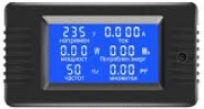
The PZEM-022 is a multifunctional energy meter designed for monitoring and measuring key electrical parameters in AC circuits. It provides accurate readings of voltage, current, power, energy consumption, and frequency. Equipped with a digital display, the PZEM-022 allows for real-time monitoring, while its UART communication interface enables data logging and remote monitoring applications. This makes it an ideal choice for industrial automation, home energy management systems, and laboratory testing setups.
Explore Projects Built with PZEM-022
 Open Project in Cirkit Designer
 Open Project in Cirkit Designer
 Open Project in Cirkit Designer
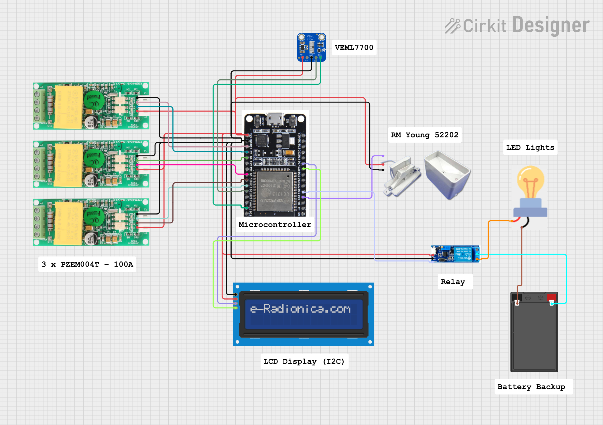 Open Project in Cirkit Designer
Explore Projects Built with PZEM-022
Open Project in Cirkit DesignerOpen Project in Cirkit DesignerOpen Project in Cirkit DesignerOpen Project in Cirkit DesignerCommon Applications
- Home energy monitoring systems
- Industrial equipment power measurement
- Laboratory testing and research
- Renewable energy systems (e.g., solar inverters)
- Data logging and remote monitoring via UART
Technical Specifications
The PZEM-022 is designed to operate in a wide range of AC applications. Below are its key technical specifications:
| Parameter | Specification |
|---|---|
| Voltage Range | 80V - 260V AC |
| Current Range | 0A - 100A (with external current transformer) |
| Power Range | 0W - 22kW |
| Energy Range | 0kWh - 9999kWh |
| Frequency Range | 45Hz - 65Hz |
| Accuracy | ±0.5% |
| Communication Protocol | UART (9600 baud rate) |
| Power Supply | Self-powered (via measured AC line) |
| Display Type | Digital LCD |
| Operating Temperature | -10°C to 60°C |
| Dimensions | 79mm x 43mm x 48mm |
Pin Configuration and Descriptions
The PZEM-022 has a simple wiring interface for both power measurement and UART communication. Below is the pin configuration:
Power Measurement Terminals
| Terminal | Description |
|---|---|
| L (Line) | Connect to the live AC wire |
| N (Neutral) | Connect to the neutral AC wire |
UART Communication Pins
| Pin | Description |
|---|---|
| TX | Transmit data (connect to RX of microcontroller) |
| RX | Receive data (connect to TX of microcontroller) |
| GND | Ground (common ground with microcontroller) |
Usage Instructions
Connecting the PZEM-022
Power Measurement Setup:
- Connect the "L" terminal to the live AC wire.
- Connect the "N" terminal to the neutral AC wire.
- Ensure proper insulation and safety precautions when working with high-voltage AC circuits.
Current Transformer (CT) Installation:
- Place the external CT around the live wire of the AC circuit.
- Ensure the CT is oriented correctly (arrow on CT should point toward the load).
UART Communication:
- Connect the TX pin of the PZEM-022 to the RX pin of your microcontroller (e.g., Arduino UNO).
- Connect the RX pin of the PZEM-022 to the TX pin of your microcontroller.
- Connect the GND pin of the PZEM-022 to the GND of your microcontroller.
Important Considerations
- Safety First: Always disconnect power before wiring the PZEM-022 to avoid electric shock.
- Voltage Range: Ensure the AC voltage is within the specified range (80V - 260V AC).
- UART Communication: Use a logic level converter if your microcontroller operates at 3.3V logic levels, as the PZEM-022 uses 5V logic.
Example Code for Arduino UNO
Below is an example Arduino sketch to read data from the PZEM-022 using UART communication:
#include <SoftwareSerial.h>

// Define RX and TX pins for SoftwareSerial
SoftwareSerial pzemSerial(10, 11); // RX = pin 10, TX = pin 11

void setup() {
  Serial.begin(9600); // Initialize Serial Monitor
  pzemSerial.begin(9600); // Initialize PZEM-022 communication

  Serial.println("PZEM-022 Energy Meter Example");
}

void loop() {
  // Request data from PZEM-022
  pzemSerial.write(0xB0); // Example command to request data (check datasheet)

  delay(100); // Wait for response

  // Read response from PZEM-022
  while (pzemSerial.available()) {
    byte data = pzemSerial.read();
    Serial.print("Received: ");
    Serial.println(data, HEX); // Print data in hexadecimal format
  }

  delay(1000); // Wait 1 second before next request
}
Notes:
- Replace the
0xB0command with the appropriate command based on the PZEM-022 datasheet. - Ensure the RX and TX pins are correctly connected to the Arduino.
Troubleshooting and FAQs
Common Issues
No Data Received via UART:
- Cause: Incorrect wiring or baud rate mismatch.
- Solution: Verify the TX and RX connections. Ensure the baud rate is set to 9600.
Incorrect Measurements:
- Cause: Improper CT installation or loose connections.
- Solution: Ensure the CT is securely clamped around the live wire and oriented correctly.
Display Not Turning On:
- Cause: No power supply to the PZEM-022.
- Solution: Check the AC connections to the "L" and "N" terminals.
UART Communication Interference:
- Cause: Long UART cables or noisy environment.
- Solution: Use shorter cables or shielded wires for UART communication.
FAQs
Q1: Can the PZEM-022 measure DC circuits?
A1: No, the PZEM-022 is designed specifically for AC circuits and cannot measure DC parameters.
Q2: Is the PZEM-022 compatible with 3.3V microcontrollers?
A2: Yes, but you will need a logic level converter to safely interface the 5V UART signals with a 3.3V microcontroller.
Q3: Can I reset the energy reading to zero?
A3: Yes, the PZEM-022 supports a reset command via UART. Refer to the datasheet for the specific command.
Q4: What is the maximum cable length for the CT?
A4: The CT cable should ideally be kept under 1 meter to minimize signal loss and interference.
By following this documentation, you can effectively integrate the PZEM-022 into your projects for accurate energy monitoring and data logging.