Cirkit Designer Logo
Cirkit Designer
Your all-in-one circuit design IDE
Home / 
Component Documentation

How to Use 1X 12 Position Power Distribution Board PCB007: Examples, Pinouts, and Specs

Image of 1X 12 Position Power Distribution Board PCB007
Cirkit Designer LogoDesign with 1X 12 Position Power Distribution Board PCB007 in Cirkit Designer

Introduction

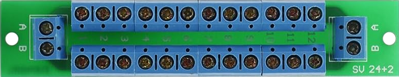
The 1X 12 Position Power Distribution Board PCB007 by Evemodel is a versatile and efficient power distribution solution designed to manage and distribute electrical power to multiple circuits. With 12 connection positions, this board is ideal for organizing power connections in complex electronic projects, ensuring a clean and reliable power supply to various components.

Explore Projects Built with 1X 12 Position Power Distribution Board PCB007

Use Cirkit Designer to design, explore, and prototype these projects online. Some projects support real-time simulation. Click "Open Project" to start designing instantly!
Industrial Power Distribution and Safety Control System
Image of Control Diagram: A project utilizing 1X 12 Position Power Distribution Board PCB007 in a practical application
This circuit is designed for power distribution and safety control in an industrial setting. It features a main isolator and circuit breaker for power management, multiple PSUs for 5V, 12V, and 24V outputs, and a safety relay system that interfaces with E-stop buttons and a start switch to control a main contactor, ensuring safe operation and emergency power cut-off capabilities.
Cirkit Designer LogoOpen Project in Cirkit Designer
Multi-Stage Voltage Regulation and Indicator LED Circuit
Image of Subramanyak_Power_Circuit: A project utilizing 1X 12 Position Power Distribution Board PCB007 in a practical application
This circuit is designed for power management, featuring buck and boost converters for voltage adjustment, and linear regulators for stable voltage output. It includes LEDs for status indication, and terminal blocks for external connections.
Cirkit Designer LogoOpen Project in Cirkit Designer
12V UPS System with Dual 18650 Li-ion Battery Backup and Voltage Regulation
Image of Power supply: A project utilizing 1X 12 Position Power Distribution Board PCB007 in a practical application
This circuit is designed to provide an uninterruptible power supply (UPS) system with a 12V DC output. It includes a 12V 5A power supply connected to an AC source through a toggle switch, which charges a pair of 18650 Li-ion batteries via a voltage regulator (XL4016). The UPS module ensures a continuous power supply to the load by switching between the power supply and the battery bank.
Cirkit Designer LogoOpen Project in Cirkit Designer
Dual 5V Power Supply Distribution Circuit with Toggle Switch Control
Image of rfdriver: A project utilizing 1X 12 Position Power Distribution Board PCB007 in a practical application
This circuit consists of two 5V 5A power supplies connected to an AC wall plug point, providing DC output through a 12-way connector. The ground connections from both power supplies are interconnected and also connected to the ground pins of two toggle switches. The DC outputs from the power supplies are separately connected to different pins on the 12-way connector, with each power supply output being switchable via one of the toggle switches.
Cirkit Designer LogoOpen Project in Cirkit Designer

Explore Projects Built with 1X 12 Position Power Distribution Board PCB007

Use Cirkit Designer to design, explore, and prototype these projects online. Some projects support real-time simulation. Click "Open Project" to start designing instantly!
Image of Control Diagram: A project utilizing 1X 12 Position Power Distribution Board PCB007 in a practical application
Industrial Power Distribution and Safety Control System
This circuit is designed for power distribution and safety control in an industrial setting. It features a main isolator and circuit breaker for power management, multiple PSUs for 5V, 12V, and 24V outputs, and a safety relay system that interfaces with E-stop buttons and a start switch to control a main contactor, ensuring safe operation and emergency power cut-off capabilities.
Cirkit Designer LogoOpen Project in Cirkit Designer
Image of Subramanyak_Power_Circuit: A project utilizing 1X 12 Position Power Distribution Board PCB007 in a practical application
Multi-Stage Voltage Regulation and Indicator LED Circuit
This circuit is designed for power management, featuring buck and boost converters for voltage adjustment, and linear regulators for stable voltage output. It includes LEDs for status indication, and terminal blocks for external connections.
Cirkit Designer LogoOpen Project in Cirkit Designer
Image of Power supply: A project utilizing 1X 12 Position Power Distribution Board PCB007 in a practical application
12V UPS System with Dual 18650 Li-ion Battery Backup and Voltage Regulation
This circuit is designed to provide an uninterruptible power supply (UPS) system with a 12V DC output. It includes a 12V 5A power supply connected to an AC source through a toggle switch, which charges a pair of 18650 Li-ion batteries via a voltage regulator (XL4016). The UPS module ensures a continuous power supply to the load by switching between the power supply and the battery bank.
Cirkit Designer LogoOpen Project in Cirkit Designer
Image of rfdriver: A project utilizing 1X 12 Position Power Distribution Board PCB007 in a practical application
Dual 5V Power Supply Distribution Circuit with Toggle Switch Control
This circuit consists of two 5V 5A power supplies connected to an AC wall plug point, providing DC output through a 12-way connector. The ground connections from both power supplies are interconnected and also connected to the ground pins of two toggle switches. The DC outputs from the power supplies are separately connected to different pins on the 12-way connector, with each power supply output being switchable via one of the toggle switches.
Cirkit Designer LogoOpen Project in Cirkit Designer

Common Applications and Use Cases

  • Model railroads and train layouts
  • Robotics and automation systems
  • LED lighting arrays
  • DIY electronics projects requiring multiple power connections
  • Prototyping and testing circuits

Technical Specifications

The following table outlines the key technical details of the PCB007 power distribution board:

Specification Details
Manufacturer Evemodel
Part ID PCB007
Number of Positions 12
Voltage Rating 0–24V DC
Maximum Current Rating 15A
Board Dimensions 70mm x 20mm
Mounting Holes 2 (for secure installation)
Terminal Type Screw terminals
PCB Material FR4 (Flame Retardant)
Operating Temperature -20°C to 85°C

Pin Configuration and Descriptions

The PCB007 features 12 screw terminal positions, divided into two rows for easy connection. Below is the pin configuration:

Position Description
1–6 Positive power distribution points
7–12 Negative (ground) distribution points

Each terminal is clearly labeled on the board for quick identification during installation.

Usage Instructions

How to Use the Component in a Circuit

  1. Power Input: Connect the main power source (e.g., a DC power supply) to one of the positive (+) and negative (-) terminals on the board.
  2. Power Distribution: Use the remaining terminals to connect individual circuits or components that require power. Ensure proper polarity when connecting devices.
  3. Securing Connections: Tighten the screw terminals securely to avoid loose connections, which can lead to power interruptions or short circuits.
  4. Mounting: Use the mounting holes to secure the board to a stable surface, such as a project enclosure or a wooden base.

Important Considerations and Best Practices

  • Voltage and Current Limits: Ensure the total voltage and current do not exceed the board's maximum ratings (24V DC and 15A).
  • Wire Gauge: Use appropriate wire gauges for your connections. For high-current applications, use thicker wires to minimize resistance and heat.
  • Polarity: Double-check the polarity of all connections to prevent damage to your components.
  • Short Circuit Protection: Consider adding a fuse or circuit breaker to your power supply to protect the board and connected devices from short circuits.

Example: Connecting to an Arduino UNO

The PCB007 can be used to distribute power to an Arduino UNO and other peripherals. Below is an example setup:

  1. Connect a 12V DC power supply to the PCB007.
  2. Use one positive and one negative terminal to power the Arduino UNO via its VIN and GND pins.
  3. Use other terminals to power additional components, such as sensors or motors.

Sample Arduino Code for a Simple LED Circuit

// This code demonstrates how to blink an LED connected to an Arduino UNO
// powered via the PCB007 power distribution board.

const int ledPin = 13; // Pin connected to the LED

void setup() {
  pinMode(ledPin, OUTPUT); // Set the LED pin as an output
}

void loop() {
  digitalWrite(ledPin, HIGH); // Turn the LED on
  delay(1000);                // Wait for 1 second
  digitalWrite(ledPin, LOW);  // Turn the LED off
  delay(1000);                // Wait for 1 second
}

Troubleshooting and FAQs

Common Issues and Solutions

  1. Loose Connections:

    • Issue: Devices intermittently lose power.
    • Solution: Ensure all screw terminals are tightened securely. Check for frayed wires.
  2. Overheating:

    • Issue: The board or wires become hot during operation.
    • Solution: Verify that the total current does not exceed 15A. Use thicker wires for high-current applications.
  3. No Power to Connected Devices:

    • Issue: Devices connected to the board do not power on.
    • Solution: Check the polarity of the connections and ensure the power source is functioning correctly.
  4. Short Circuit:

    • Issue: Sparks or power supply shuts off.
    • Solution: Inspect all connections for exposed wires or incorrect polarity. Add a fuse for protection.

FAQs

Q1: Can I use the PCB007 with an AC power source?
A1: No, the PCB007 is designed for DC power only. Using AC power may damage the board and connected devices.

Q2: What is the maximum wire size the terminals can accommodate?
A2: The screw terminals can accommodate wires up to 14 AWG.

Q3: Can I use this board for high-power applications like motors?
A3: Yes, as long as the total current does not exceed 15A. For motors with high inrush currents, consider using a relay or motor driver.

Q4: Is the board protected against reverse polarity?
A4: No, the PCB007 does not have built-in reverse polarity protection. Always double-check your connections.

By following this documentation, you can effectively utilize the 1X 12 Position Power Distribution Board PCB007 in your projects, ensuring reliable and organized power distribution.