How to Use Connector 2 In 10 Out: Examples, Pinouts, and Specs
Introduction
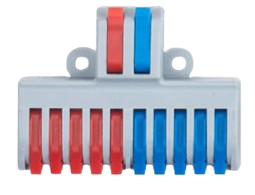
The Connector 2 In 10 Out is a versatile signal distribution component designed to route two input signals to ten output channels. This component is widely used in audio systems, data communication networks, and other applications requiring efficient signal splitting and distribution. Its compact design and reliable performance make it an essential tool for managing multiple output connections from a limited number of input sources.
Explore Projects Built with Connector 2 In 10 Out
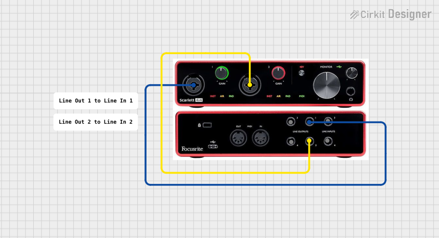


Explore Projects Built with Connector 2 In 10 Out
Common Applications and Use Cases
- Audio Systems: Distributing stereo audio signals to multiple speakers or amplifiers.
- Data Communication: Splitting data signals for parallel processing or distribution.
- Testing and Prototyping: Routing signals to multiple test points or devices.
- Home Automation: Distributing control signals to multiple devices in a smart home setup.
Technical Specifications
The Connector 2 In 10 Out is designed to handle a variety of signal types, including analog and digital signals. Below are its key technical details:
General Specifications
| Parameter | Value |
|---|---|
| Input Channels | 2 |
| Output Channels | 10 |
| Signal Type | Analog and Digital |
| Maximum Voltage | 24V DC |
| Maximum Current | 1A per channel |
| Operating Temperature | -20°C to 70°C |
| Connector Type | Screw Terminal or Pin Header |
| Dimensions | 50mm x 30mm x 15mm |
Pin Configuration and Descriptions
The Connector 2 In 10 Out has a straightforward pin layout for easy integration into circuits. Below is the pin configuration:
Input Pins
| Pin Number | Label | Description |
|---|---|---|
| 1 | IN1 | Input signal 1 |
| 2 | IN2 | Input signal 2 |
Output Pins
| Pin Number | Label | Description |
|---|---|---|
| 3-7 | OUT1-5 | Outputs for Input 1 |
| 8-12 | OUT6-10 | Outputs for Input 2 |
Power and Ground
| Pin Number | Label | Description |
|---|---|---|
| 13 | VCC | Power supply (up to 24V DC) |
| 14 | GND | Ground connection |
Usage Instructions
How to Use the Component in a Circuit
- Connect the Inputs: Attach the input signals to the
IN1andIN2pins. Ensure the signals are within the voltage and current limits specified in the technical specifications. - Connect the Outputs: Attach the devices or circuits requiring the distributed signals to the
OUT1-10pins. OutputsOUT1-5correspond toIN1, andOUT6-10correspond toIN2. - Power the Connector: Provide a suitable power supply to the
VCCandGNDpins. Ensure the power supply matches the voltage and current requirements. - Verify Connections: Double-check all connections to ensure proper signal routing and avoid short circuits.
Important Considerations and Best Practices
- Signal Integrity: Use shielded cables for input and output connections to minimize noise and signal degradation.
- Power Supply: Ensure the power supply is stable and within the specified voltage range to avoid damage to the component.
- Load Matching: Verify that the connected devices do not exceed the maximum current rating of 1A per channel.
- Mounting: Secure the connector on a stable surface to prevent accidental disconnections.
Example: Using with an Arduino UNO
The Connector 2 In 10 Out can be used with an Arduino UNO to distribute control signals. Below is an example code snippet to send signals to the connector:
// Example: Sending signals to Connector 2 In 10 Out using Arduino UNO

// Define input pins for the connector
const int input1 = 2; // Arduino pin connected to IN1
const int input2 = 3; // Arduino pin connected to IN2

void setup() {
  // Set input pins as outputs
  pinMode(input1, OUTPUT);
  pinMode(input2, OUTPUT);
}

void loop() {
  // Send HIGH signal to IN1 and LOW signal to IN2
  digitalWrite(input1, HIGH); // Signal to OUT1-5
  digitalWrite(input2, LOW);  // Signal to OUT6-10

  delay(1000); // Wait for 1 second

  // Alternate the signals
  digitalWrite(input1, LOW);  // Signal to OUT1-5
  digitalWrite(input2, HIGH); // Signal to OUT6-10

  delay(1000); // Wait for 1 second
}
Troubleshooting and FAQs
Common Issues and Solutions
No Signal at Outputs:
- Cause: Input signals are not connected or are outside the specified range.
- Solution: Verify the input connections and ensure the signals are within the voltage and current limits.
Signal Degradation or Noise:
- Cause: Poor-quality cables or interference from nearby components.
- Solution: Use shielded cables and maintain proper spacing between the connector and other components.
Overheating:
- Cause: Exceeding the maximum current rating of 1A per channel.
- Solution: Reduce the load on the outputs or use a heat sink if necessary.
Intermittent Connections:
- Cause: Loose or improperly secured wires.
- Solution: Ensure all wires are securely fastened to the screw terminals or pin headers.
FAQs
Q1: Can this connector handle AC signals?
A1: Yes, the connector can handle low-frequency AC signals, provided they are within the voltage and current limits.
Q2: Can I use fewer than 10 outputs?
A2: Yes, you can use as many outputs as needed. Unused outputs will remain inactive.
Q3: Is this connector suitable for high-frequency signals?
A3: The connector is best suited for low- to mid-frequency signals. For high-frequency applications, ensure proper impedance matching and shielding.
Q4: Can I use this connector without a power supply?
A4: No, the connector requires a power supply to function correctly. Ensure the power supply matches the specified requirements.