Cirkit Designer Logo
Cirkit Designer
Your all-in-one circuit design IDE
Home / 
Component Documentation

How to Use Real Time Clock Module - DS1307 RTC Breakout Board: Examples, Pinouts, and Specs

Image of Real Time Clock Module - DS1307 RTC Breakout Board
Cirkit Designer LogoDesign with Real Time Clock Module - DS1307 RTC Breakout Board in Cirkit Designer

Introduction

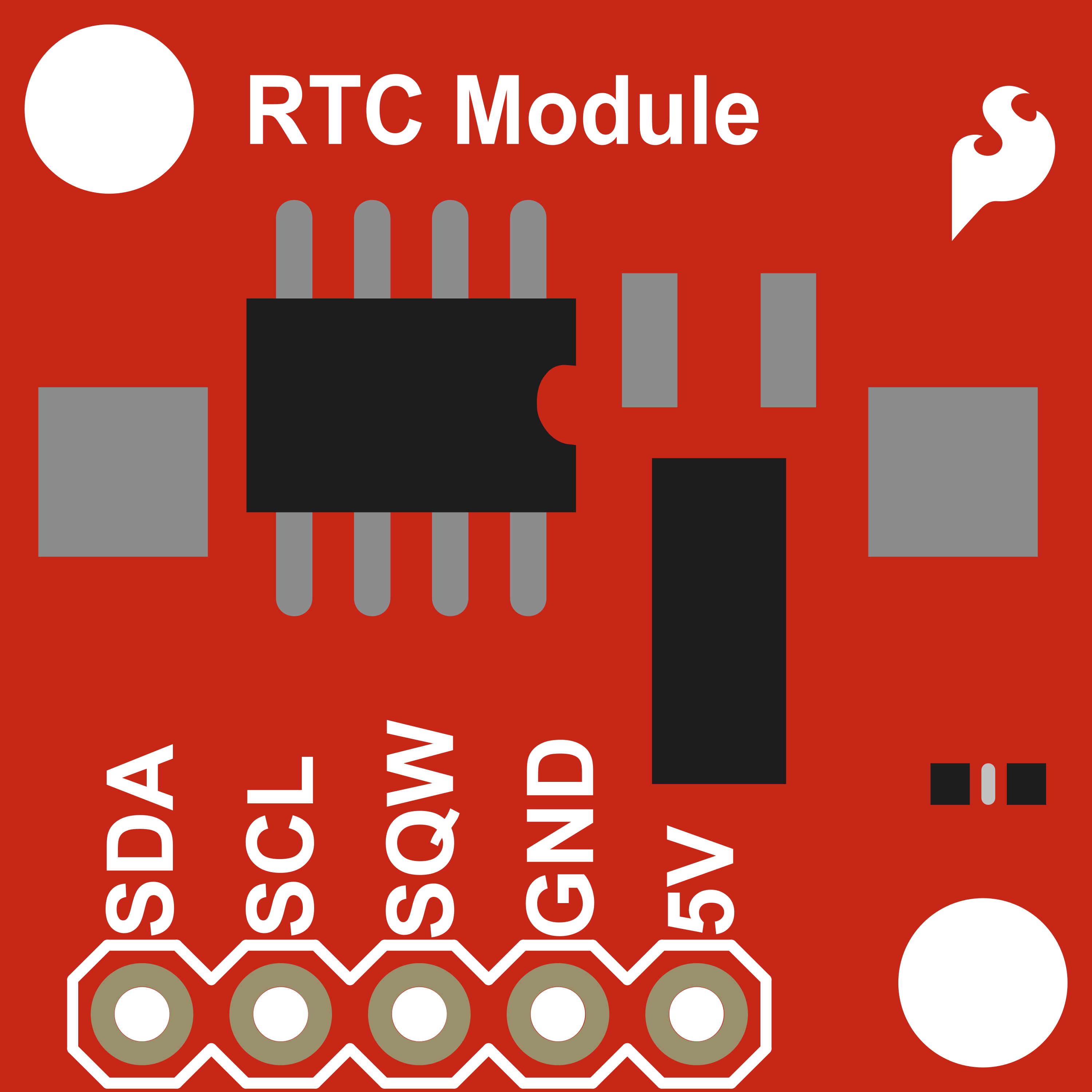
The DS1307 Real Time Clock (RTC) Module is a low-power, full binary-coded decimal (BCD) clock/calendar with 56 bytes of NV SRAM. It provides precise timekeeping with a built-in 32.768 kHz crystal oscillator. Common applications include timekeeping in embedded systems, logging events with timestamps, and maintaining accurate time across power cycles in devices like digital clocks, attendance systems, and data loggers.

Explore Projects Built with Real Time Clock Module - DS1307 RTC Breakout Board

Use Cirkit Designer to design, explore, and prototype these projects online. Some projects support real-time simulation. Click "Open Project" to start designing instantly!
Arduino UNO-Based Real-Time Clock with I2C LCD Display and IO Expansion
Image of teste: A project utilizing Real Time Clock Module - DS1307 RTC Breakout Board in a practical application
This circuit is an Arduino-based real-time clock and display system. It uses an Arduino UNO to interface with a DS1307 RTC module for timekeeping and a 20x4 I2C LCD to display the current time and date. Additionally, a PCF8574 IO Expansion Board is used to extend the I2C bus for additional I/O operations.
Cirkit Designer LogoOpen Project in Cirkit Designer
Arduino UNO with DS1307 RTC Controlled LED Lighting System
Image of li8: A project utilizing Real Time Clock Module - DS1307 RTC Breakout Board in a practical application
This circuit features an Arduino UNO connected to a DS1307 Real Time Clock (RTC) module for timekeeping and a red LED with a series resistor for indication purposes. The Arduino communicates with the RTC via I2C (using A4 and A5 pins for SDA and SCL, respectively), and controls the LED connected to digital pin D8 through a 330-ohm resistor. The embedded code sets the RTC time, checks the current time, and turns the LED on or off based on the specified time condition (between 11:00 AM and 11:43 AM).
Cirkit Designer LogoOpen Project in Cirkit Designer
Arduino Nano Based Real-Time Clock Display with TM1637
Image of 7segmant: A project utilizing Real Time Clock Module - DS1307 RTC Breakout Board in a practical application
This circuit features an Arduino Nano interfacing with a DS3231 Real-Time Clock for timekeeping and a TM1637 display module for visual output. The Arduino facilitates I2C communication with the RTC and controls the display using digital IO, serving as the central processing unit for a digital clock or timer application.
Cirkit Designer LogoOpen Project in Cirkit Designer
Arduino UNO Real-Time Clock with DS1307 RTC Module
Image of rrtc: A project utilizing Real Time Clock Module - DS1307 RTC Breakout Board in a practical application
This circuit interfaces an Arduino UNO with a DS1307 Real-Time Clock (RTC) module. The Arduino communicates with the RTC module using the I2C protocol, with connections from A4 to SDA and A5 to SCL.
Cirkit Designer LogoOpen Project in Cirkit Designer

Explore Projects Built with Real Time Clock Module - DS1307 RTC Breakout Board

Use Cirkit Designer to design, explore, and prototype these projects online. Some projects support real-time simulation. Click "Open Project" to start designing instantly!
Image of teste: A project utilizing Real Time Clock Module - DS1307 RTC Breakout Board in a practical application
Arduino UNO-Based Real-Time Clock with I2C LCD Display and IO Expansion
This circuit is an Arduino-based real-time clock and display system. It uses an Arduino UNO to interface with a DS1307 RTC module for timekeeping and a 20x4 I2C LCD to display the current time and date. Additionally, a PCF8574 IO Expansion Board is used to extend the I2C bus for additional I/O operations.
Cirkit Designer LogoOpen Project in Cirkit Designer
Image of li8: A project utilizing Real Time Clock Module - DS1307 RTC Breakout Board in a practical application
Arduino UNO with DS1307 RTC Controlled LED Lighting System
This circuit features an Arduino UNO connected to a DS1307 Real Time Clock (RTC) module for timekeeping and a red LED with a series resistor for indication purposes. The Arduino communicates with the RTC via I2C (using A4 and A5 pins for SDA and SCL, respectively), and controls the LED connected to digital pin D8 through a 330-ohm resistor. The embedded code sets the RTC time, checks the current time, and turns the LED on or off based on the specified time condition (between 11:00 AM and 11:43 AM).
Cirkit Designer LogoOpen Project in Cirkit Designer
Image of 7segmant: A project utilizing Real Time Clock Module - DS1307 RTC Breakout Board in a practical application
Arduino Nano Based Real-Time Clock Display with TM1637
This circuit features an Arduino Nano interfacing with a DS3231 Real-Time Clock for timekeeping and a TM1637 display module for visual output. The Arduino facilitates I2C communication with the RTC and controls the display using digital IO, serving as the central processing unit for a digital clock or timer application.
Cirkit Designer LogoOpen Project in Cirkit Designer
Image of rrtc: A project utilizing Real Time Clock Module - DS1307 RTC Breakout Board in a practical application
Arduino UNO Real-Time Clock with DS1307 RTC Module
This circuit interfaces an Arduino UNO with a DS1307 Real-Time Clock (RTC) module. The Arduino communicates with the RTC module using the I2C protocol, with connections from A4 to SDA and A5 to SCL.
Cirkit Designer LogoOpen Project in Cirkit Designer

Technical Specifications

Key Features

  • Voltage Supply: 4.5V to 5.5V
  • Current: Less than 200μA at 5V
  • Timekeeping Format: Hours, Minutes, Seconds, AM/PM
  • Date Format: Day, Date, Month, Year
  • Memory: 56 Bytes of NV SRAM
  • Communication: I2C Serial Interface
  • Battery Backup: Yes (Coin Cell)

Pin Configuration

Pin Number Pin Name Description
1 VCC Power supply (4.5V to 5.5V)
2 GND Ground
3 SDA Serial Data Line for I2C communication
4 SCL Serial Clock Line for I2C communication
5 SQW/OUT Square Wave/Output Driver (Not always used)
6 32K 32kHz Output (Not always used)
7 BAT Battery Input for Backup

Usage Instructions

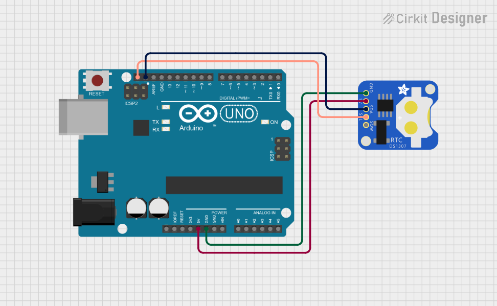
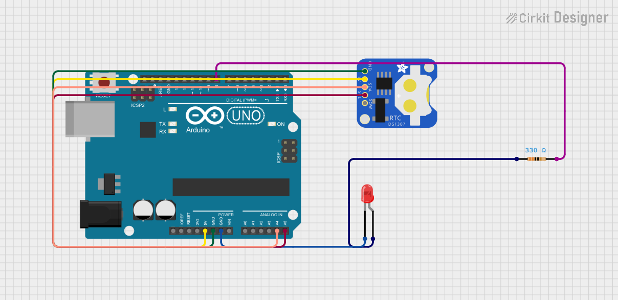
Interfacing with a Circuit

  1. Connect the VCC pin to a 5V power supply.
  2. Connect the GND pin to the ground of the power supply.
  3. Connect the SDA and SCL pins to the I2C data and clock lines, respectively.
  4. Optionally, connect the SQW/OUT pin if a square wave output is required.
  5. Insert a coin cell battery into the battery holder for backup power.

Best Practices

  • Ensure that the power supply is within the specified range.
  • Use pull-up resistors on the SDA and SCL lines, typically 4.7kΩ.
  • Avoid placing the module near heat sources or in environments with extreme temperatures.
  • When using battery backup, check the battery voltage regularly and replace it when necessary.

Example Code for Arduino UNO

#include <Wire.h>
#include "RTClib.h"

RTC_DS1307 rtc;

void setup() {
  Serial.begin(9600);
  if (!rtc.begin()) {
    Serial.println("Couldn't find RTC");
    while (1);
  }

  if (!rtc.isrunning()) {
    Serial.println("RTC is NOT running!");
    // Following line sets the RTC to the date & time this sketch was compiled
    rtc.adjust(DateTime(F(__DATE__), F(__TIME__)));
  }
}

void loop() {
  DateTime now = rtc.now();

  Serial.print(now.year(), DEC);
  Serial.print('/');
  Serial.print(now.month(), DEC);
  Serial.print('/');
  Serial.print(now.day(), DEC);
  Serial.print(" ");
  Serial.print(now.hour(), DEC);
  Serial.print(':');
  Serial.print(now.minute(), DEC);
  Serial.print(':');
  Serial.print(now.second(), DEC);
  Serial.println();

  delay(1000);
}

Troubleshooting and FAQs

Common Issues

  • Time not updating: Ensure the battery is properly installed and has charge.
  • I2C communication failure: Check the wiring, and ensure pull-up resistors are in place.
  • Incorrect time after power cycle: Make sure the RTC module has a working battery for backup.

FAQs

Q: How do I set the time on the DS1307 RTC? A: You can set the time by using the rtc.adjust(DateTime(__DATE__, __TIME__)); function in your setup routine.

Q: What is the life expectancy of the backup battery? A: The battery life depends on the quality of the battery but typically lasts for several years.

Q: Can the DS1307 RTC module work without an Arduino? A: Yes, it can work with any microcontroller that supports I2C communication.

Q: Is it necessary to use a 32.768 kHz crystal with the DS1307? A: The DS1307 RTC module typically comes with a built-in 32.768 kHz crystal. It is crucial for accurate timekeeping and should not be removed or replaced.

For further assistance, consult the datasheet of the DS1307 RTC module or contact technical support.