How to Use DC2708A: Examples, Pinouts, and Specs
Introduction
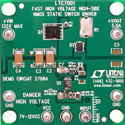
The DC2708A is a demonstration circuit developed by Analog Devices to evaluate the performance of the LTC3105, a high-efficiency, low-voltage boost converter. The LTC3105 is specifically designed for energy harvesting applications, enabling the conversion of low input voltages from sources such as solar cells or thermoelectric generators into higher, usable output voltages. This makes the DC2708A an ideal tool for testing and prototyping energy harvesting systems.
Explore Projects Built with DC2708A


Explore Projects Built with DC2708A
Common Applications and Use Cases
- Energy harvesting from solar cells, thermoelectric generators, or piezoelectric devices.
- Powering low-power wireless sensors and IoT devices.
- Battery charging in low-energy environments.
- Applications requiring efficient conversion of low input voltages to higher output voltages.
Technical Specifications
Key Technical Details
- Input Voltage Range: 0.2V to 5V
- Output Voltage Range: Configurable up to 5.25V
- Maximum Output Current: Dependent on input voltage and source capability (up to 100mA typical).
- Efficiency: Up to 94% (depending on input/output conditions).
- Integrated MPPT (Maximum Power Point Tracking): Optimized for energy harvesting sources.
- Quiescent Current: 24µA (typical).
- Operating Temperature Range: -40°C to 125°C.
Pin Configuration and Descriptions
The DC2708A demonstration board includes several key pins and connectors for evaluation. Below is a table describing the main connections:
| Pin/Connector | Description |
|---|---|
| VIN | Input voltage terminal. Connect the energy source (e.g., solar cell or TEG). |
| VOUT | Output voltage terminal. Provides the boosted output voltage. |
| GND | Ground connection. Common ground for input and output. |
| MPPC | Maximum Power Point Control pin. Used to set the MPPT voltage. |
| SHDN | Shutdown pin. Pull low to disable the LTC3105; pull high to enable it. |
| FB | Feedback pin. Used to set the output voltage via an external resistor divider. |
| L1, L2 | Inductor connection points for the boost converter circuit. |
| JP1 | Jumper to enable or disable the MPPT functionality. |
Usage Instructions
How to Use the DC2708A in a Circuit
- Connect the Input Source: Attach the energy harvesting source (e.g., a solar cell or thermoelectric generator) to the VIN and GND terminals.
- Set the Output Voltage: Use the onboard resistor divider or external resistors connected to the FB pin to configure the desired output voltage.
- Enable the Circuit: Ensure the SHDN pin is pulled high to enable the LTC3105. This can be done via a jumper or an external signal.
- Monitor MPPT: If using an energy harvesting source, configure the MPPC pin to match the source's maximum power point voltage. This ensures optimal energy conversion.
- Connect the Load: Attach the load to the VOUT and GND terminals. Ensure the load does not exceed the maximum output current capability.
Important Considerations and Best Practices
- Input Source Impedance: Ensure the input source can provide sufficient current for the desired output power. High source impedance may limit performance.
- Inductor Selection: Use an inductor with the recommended value and current rating as specified in the LTC3105 datasheet for optimal performance.
- Thermal Management: While the LTC3105 is highly efficient, ensure adequate ventilation or heat dissipation if operating at high power levels.
- MPPT Configuration: For energy harvesting applications, carefully set the MPPC voltage to match the source's maximum power point for optimal efficiency.
Example Code for Arduino UNO
The DC2708A can be used with an Arduino UNO to monitor the output voltage or control the SHDN pin. Below is an example code snippet:
// Example code to monitor the output voltage of the DC2708A using Arduino UNO
// and control the SHDN pin to enable or disable the LTC3105.

const int shdnPin = 7;  // Pin connected to the SHDN pin of the DC2708A
const int voutPin = A0; // Analog pin connected to the VOUT terminal (via a voltage divider)

void setup() {
  pinMode(shdnPin, OUTPUT);  // Set SHDN pin as output
  digitalWrite(shdnPin, HIGH); // Enable the LTC3105 by pulling SHDN high

  Serial.begin(9600);  // Initialize serial communication for monitoring
}

void loop() {
  // Read the output voltage (scaled by a voltage divider)
  int voutRaw = analogRead(voutPin);
  float voutVoltage = (voutRaw / 1023.0) * 5.0 * 2; // Adjust scaling factor as per divider

  // Print the output voltage to the serial monitor
  Serial.print("Output Voltage: ");
  Serial.print(voutVoltage);
  Serial.println(" V");

  delay(1000);  // Wait for 1 second before the next reading
}
Note: Use a voltage divider to scale the VOUT voltage to within the Arduino's 0-5V ADC range. Adjust the scaling factor in the code accordingly.
Troubleshooting and FAQs
Common Issues and Solutions
No Output Voltage:
- Ensure the SHDN pin is pulled high to enable the LTC3105.
- Verify the input source is connected and providing sufficient voltage/current.
- Check the feedback resistor configuration to ensure the output voltage is set correctly.
Low Efficiency:
- Confirm the MPPC voltage is correctly set for the input source.
- Use an inductor with the recommended specifications.
- Minimize resistive losses in the input and output connections.
Output Voltage Unstable:
- Check for proper capacitor placement and values on the input and output.
- Ensure the input source is stable and not fluctuating excessively.
Overheating:
- Verify the load current does not exceed the maximum output current capability.
- Ensure adequate ventilation or heat sinking for the circuit.
FAQs
Can the DC2708A charge a battery? Yes, the DC2708A can be used to charge small batteries, provided the output voltage and current are configured appropriately for the battery type.
What is the maximum power the DC2708A can handle? The maximum power depends on the input voltage and source capability. Refer to the LTC3105 datasheet for detailed power calculations.
Is the MPPT feature mandatory? No, the MPPT feature is optional but highly recommended for energy harvesting applications to maximize efficiency.
Can I use the DC2708A with a piezoelectric energy source? Yes, the DC2708A is compatible with piezoelectric sources, provided the input voltage is within the specified range.