How to Use LTR390-UV-01: Examples, Pinouts, and Specs
Introduction
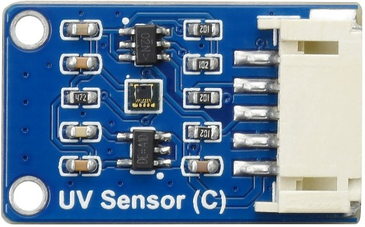
The LTR390-UV-01 is a high-performance ultraviolet (UV) light sensor manufactured by Waveshare. It is designed to detect UV light levels and provides an analog output proportional to the intensity of the UV radiation. This sensor is compact, energy-efficient, and highly sensitive, making it ideal for a wide range of applications.
Explore Projects Built with LTR390-UV-01
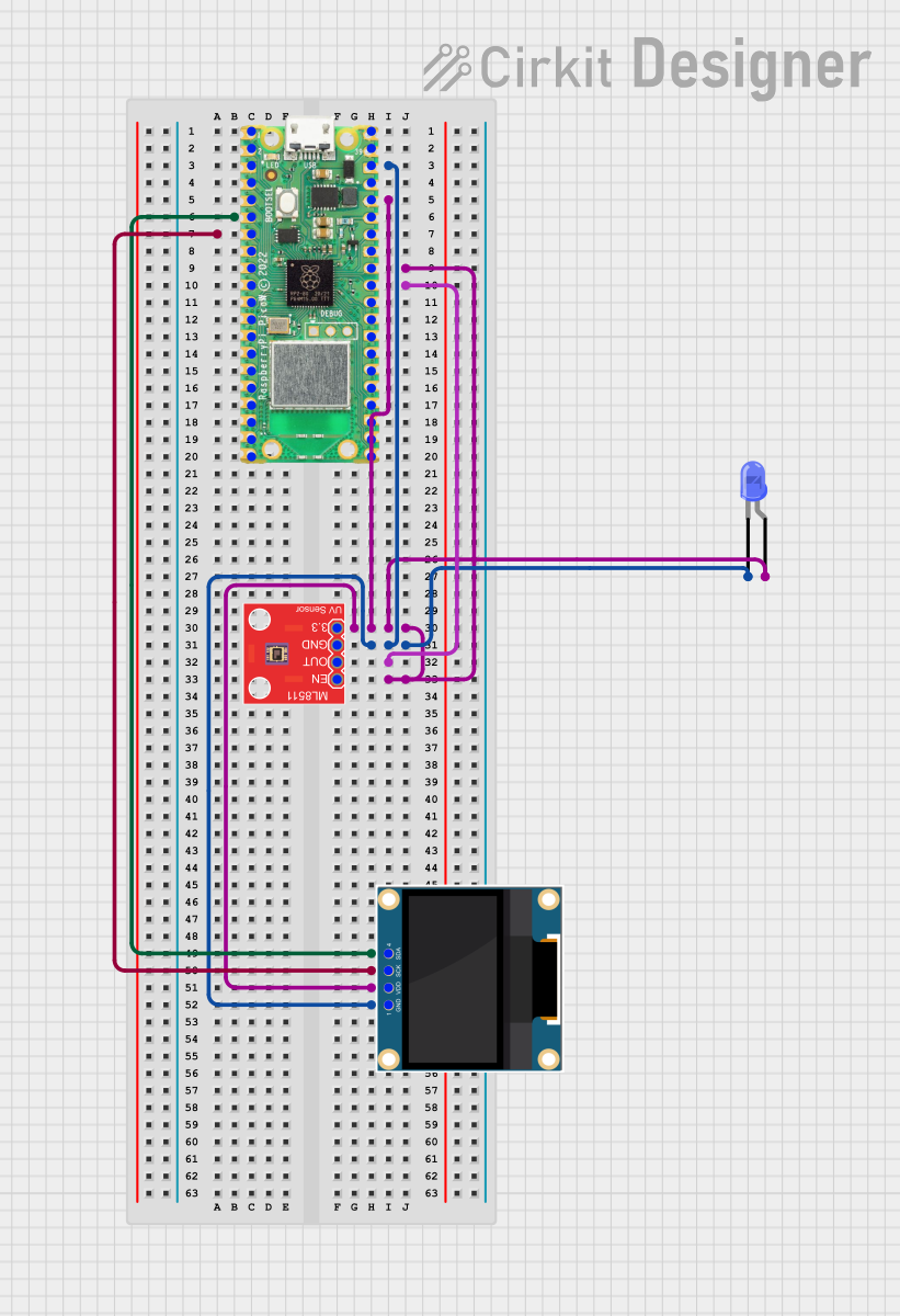
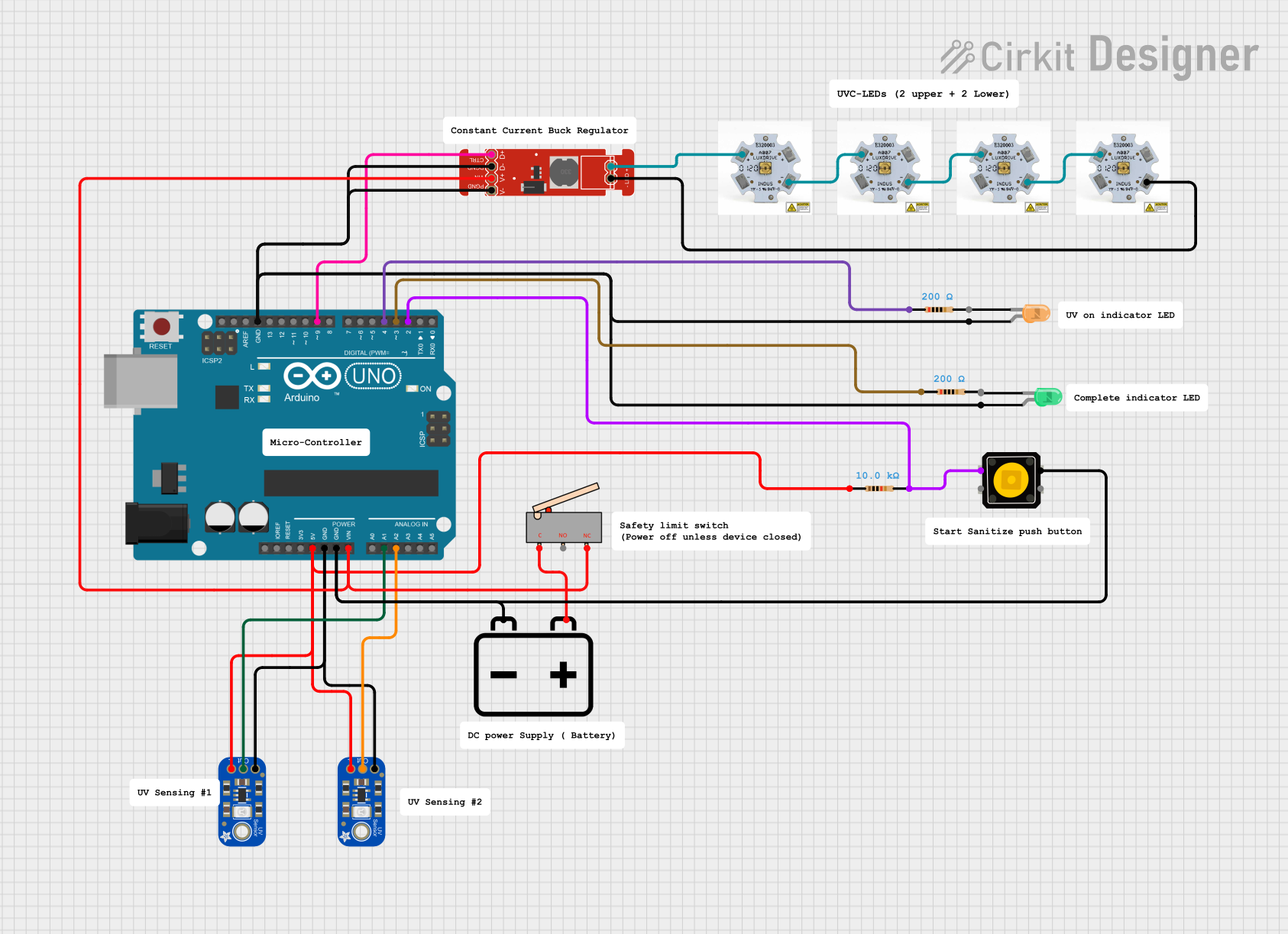

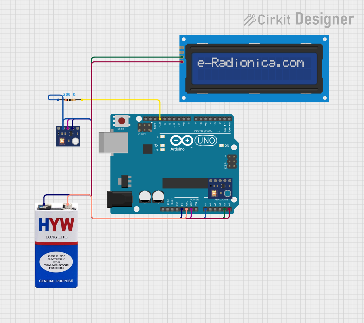
Explore Projects Built with LTR390-UV-01
Common Applications
- Environmental monitoring systems
- UV exposure measurement devices
- Wearable UV safety systems
- Smart home automation for UV-based lighting control
- Industrial UV curing and sterilization monitoring
Technical Specifications
The following table outlines the key technical details of the LTR390-UV-01 sensor:
| Parameter | Value |
|---|---|
| Operating Voltage | 3.3V to 5V |
| Operating Current | 5 µA (typical) |
| UV Wavelength Range | 280 nm to 400 nm |
| Output Type | Analog voltage |
| Operating Temperature | -40°C to +85°C |
| Communication Interface | I2C |
| Dimensions | 10 mm x 10 mm x 2 mm |
Pin Configuration
The LTR390-UV-01 sensor has a simple pinout for easy integration into circuits. The table below describes the pin configuration:
| Pin | Name | Description |
|---|---|---|
| 1 | VCC | Power supply input (3.3V to 5V) |
| 2 | GND | Ground connection |
| 3 | SDA | I2C data line |
| 4 | SCL | I2C clock line |
| 5 | INT | Interrupt output (optional, for event detection) |
Usage Instructions
How to Use the LTR390-UV-01 in a Circuit
- Power Supply: Connect the VCC pin to a 3.3V or 5V power source and the GND pin to the ground of your circuit.
- I2C Communication: Connect the SDA and SCL pins to the corresponding I2C pins on your microcontroller (e.g., Arduino UNO).
- Interrupt Pin (Optional): If you want to use the interrupt feature, connect the INT pin to a GPIO pin on your microcontroller.
- Pull-Up Resistors: Ensure that the I2C lines (SDA and SCL) have pull-up resistors (typically 4.7 kΩ) if not already present on your board.
Important Considerations
- UV Calibration: The sensor provides raw UV intensity data. You may need to calibrate it for specific applications.
- Ambient Light Interference: Avoid placing the sensor in areas with high ambient light interference to ensure accurate UV readings.
- Temperature Effects: The sensor operates reliably within its temperature range, but extreme temperatures may affect performance.
Example Code for Arduino UNO
Below is an example of how to interface the LTR390-UV-01 with an Arduino UNO using the I2C protocol:
#include <Wire.h>

// I2C address of the LTR390-UV-01 sensor
#define LTR390_ADDRESS 0x53

void setup() {
  Wire.begin(); // Initialize I2C communication
  Serial.begin(9600); // Start serial communication for debugging

  // Initialize the sensor
  Wire.beginTransmission(LTR390_ADDRESS);
  Wire.write(0x00); // Example: Write to a configuration register
  Wire.endTransmission();

  Serial.println("LTR390-UV-01 initialized.");
}

void loop() {
  uint16_t uvData = readUVData(); // Read UV intensity data
  Serial.print("UV Intensity: ");
  Serial.println(uvData);

  delay(1000); // Wait for 1 second before the next reading
}

uint16_t readUVData() {
  uint16_t uvValue = 0;

  Wire.beginTransmission(LTR390_ADDRESS);
  Wire.write(0x01); // Example: Command to read UV data
  Wire.endTransmission();

  Wire.requestFrom(LTR390_ADDRESS, 2); // Request 2 bytes of data
  if (Wire.available() == 2) {
    uvValue = Wire.read(); // Read the first byte
    uvValue |= (Wire.read() << 8); // Read the second byte and combine
  }

  return uvValue;
}
Notes on the Code
- Replace
0x00and0x01with the actual register addresses from the sensor's datasheet. - Ensure the I2C address (
0x53) matches the address of your sensor.
Troubleshooting and FAQs
Common Issues
No Data from the Sensor
- Cause: Incorrect I2C wiring or address mismatch.
- Solution: Double-check the SDA and SCL connections and verify the I2C address.
Inaccurate UV Readings
- Cause: Ambient light interference or lack of calibration.
- Solution: Shield the sensor from ambient light and perform proper calibration.
Sensor Not Detected
- Cause: Missing pull-up resistors on the I2C lines.
- Solution: Add 4.7 kΩ pull-up resistors to the SDA and SCL lines.
FAQs
Q: Can the LTR390-UV-01 measure visible light?
A: No, the sensor is specifically designed to detect UV light in the 280 nm to 400 nm range.
Q: Is the sensor waterproof?
A: No, the LTR390-UV-01 is not waterproof. Use a protective enclosure for outdoor applications.
Q: Can I use this sensor with a 3.3V microcontroller?
A: Yes, the sensor operates with both 3.3V and 5V power supplies, making it compatible with most microcontrollers.
Q: How do I calibrate the sensor?
A: Calibration involves comparing the sensor's output to a known UV intensity source and applying a correction factor in your code.
This concludes the documentation for the LTR390-UV-01 UV light sensor.