How to Use TNY278PN: Examples, Pinouts, and Specs
Introduction
The TNY278PN is a high-voltage integrated circuit designed for offline switch mode power supplies. It integrates a power MOSFET, oscillator, and control circuitry into a single package, simplifying the design of compact and efficient power supplies. This component is optimized for low power consumption and high efficiency, making it ideal for applications such as adapters, chargers, and auxiliary power supplies in appliances.
Explore Projects Built with TNY278PN


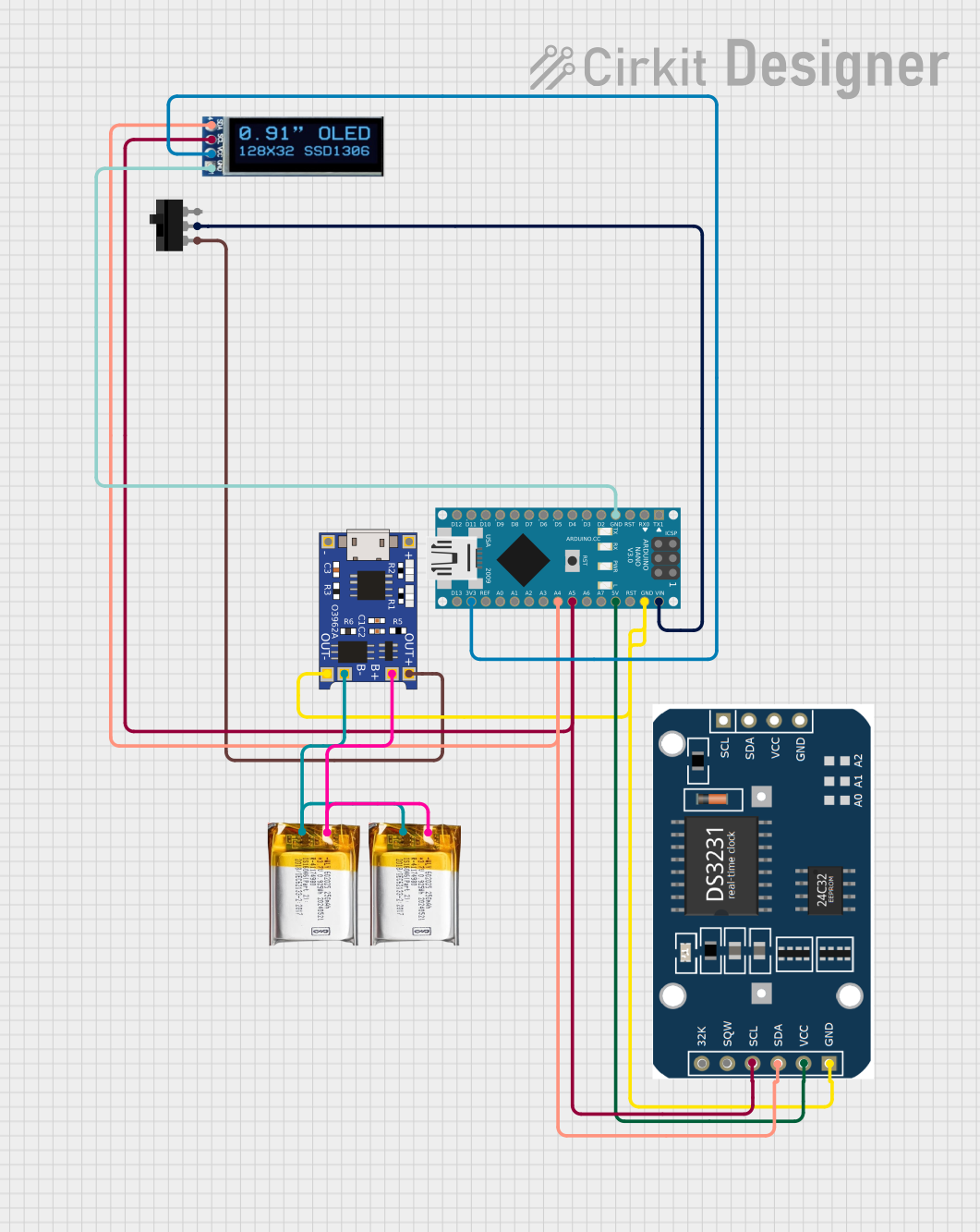
Explore Projects Built with TNY278PN
Common Applications:
- Mobile phone chargers
- Standby power supplies for TVs and set-top boxes
- Industrial control systems
- LED drivers
Technical Specifications
Key Technical Details:
- Input Voltage Range: 85 VAC to 265 VAC
- Output Power Capability: Up to 23 W (depending on input voltage and thermal conditions)
- Switching Frequency: 132 kHz (typical)
- On-State Resistance (RDS(ON)): 2.8 Ω (typical)
- Maximum Drain Current: 700 mA
- Standby Power Consumption: < 150 mW at no load
- Thermal Shutdown Protection: Yes
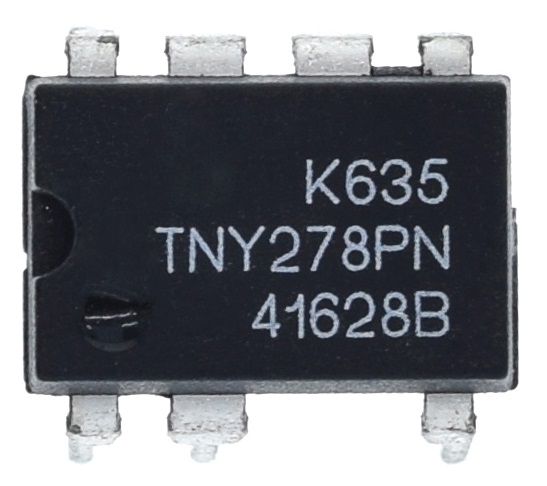
- Package Type: DIP-8 (Dual Inline Package)
Pin Configuration and Descriptions:
The TNY278PN comes in an 8-pin DIP package. Below is the pinout and description:
| Pin Number | Pin Name | Description |
|---|---|---|
| 1 | ENABLE/UNDERVOLTAGE (EN/UV) | Input for enabling/disabling the IC and undervoltage lockout. |
| 2 | SOURCE (S) | Primary return pin for the internal MOSFET. Connect to the ground of the circuit. |
| 3 | SOURCE (S) | Same as Pin 2. |
| 4 | SOURCE (S) | Same as Pin 2. |
| 5 | BP (BYPASS) | Connection for an external bypass capacitor to set the current limit. |
| 6 | DRAIN (D) | High-voltage drain pin of the internal MOSFET. Connect to the transformer. |
| 7 | DRAIN (D) | Same as Pin 6. |
| 8 | DRAIN (D) | Same as Pin 6. |
Usage Instructions
How to Use the TNY278PN in a Circuit:
Power Supply Design:
- Connect the DRAIN pin to the primary winding of the transformer.
- Use a snubber circuit (e.g., an RC network) across the transformer to suppress voltage spikes.
- Connect the SOURCE pins to the ground of the circuit.
Bypass Capacitor:
- Attach a 0.1 µF ceramic capacitor to the BP pin to stabilize the internal circuitry.
- For higher current limits, use a larger capacitor (e.g., 1 µF).
Enable/Undervoltage Pin:
- To enable the IC, ensure the voltage on the EN/UV pin is above the undervoltage threshold.
- For undervoltage lockout, connect a resistor divider to this pin to monitor the input voltage.
Thermal Management:
- Ensure adequate heat dissipation by providing proper PCB layout and, if necessary, a heatsink.
Output Regulation:
- Use an optocoupler and a feedback circuit to regulate the output voltage.
Example Circuit:
Below is a basic schematic for a 5V, 10W power supply using the TNY278PN:
AC Input --> Bridge Rectifier --> Filter Capacitor --> Transformer --> Output Rectifier
Arduino Compatibility:
The TNY278PN is not directly connected to an Arduino but can be used to power an Arduino board. For example, you can design a 5V power supply using the TNY278PN and use it to power the Arduino UNO via its 5V pin.
Troubleshooting and FAQs
Common Issues and Solutions:
No Output Voltage:
- Cause: Incorrect wiring or insufficient input voltage.
- Solution: Verify the connections and ensure the input voltage is within the specified range.
Overheating:
- Cause: Inadequate heat dissipation or excessive load.
- Solution: Improve PCB layout for better thermal management or reduce the load.
High Standby Power Consumption:
- Cause: Incorrect feedback circuit design.
- Solution: Optimize the feedback circuit and ensure proper snubber design.
Intermittent Operation:
- Cause: Insufficient bypass capacitor value.
- Solution: Use a 0.1 µF or larger capacitor on the BP pin.
FAQs:
Q1: Can the TNY278PN be used for high-power applications?
A1: The TNY278PN is designed for low to medium power applications (up to 23 W). For higher power, consider using other members of the TinySwitch family.
Q2: What type of transformer should I use?
A2: Use a flyback transformer designed for the desired output voltage and power rating. Ensure it meets the isolation requirements for your application.
Q3: How do I protect the IC from voltage spikes?
A3: Use a snubber circuit (e.g., an RC network) across the transformer primary winding to suppress voltage spikes.
Q4: Can I use the TNY278PN for multiple output voltages?
A4: Yes, you can design a multi-output flyback converter, but ensure proper feedback regulation for each output.
By following this documentation, you can effectively integrate the TNY278PN into your power supply designs.